Vibrator

A vibrator and vibrating body technology, which is applied to instruments, fluids using vibration, electromechanical clocks, etc., can solve problems such as increased manufacturing costs and difficult positioning accuracy

Inactive Publication Date: 2013-10-23
HOSIDEN CORP
View PDF8 Cites 2 Cited by
  • Summary
  • Abstract
  • Description
  • Claims
  • Application Information

AI Technical Summary

Problems solved by technology

[0006] The vibrator of Japanese Patent Application Laid-Open No. 2003-033724 has difficulty in improving the positioning accuracy of the above-mentioned coils
On the other hand, although the vibrator of Japanese Patent Laid-Open No. 2007-184812 can improve the positioning accuracy of the coil, holes for positioning are provided on each component, which increases the manufacturing cost of each component.

Method used


Image

  • Vibrator
  • Vibrator
  • Vibrator

Examples


Embodiment 1

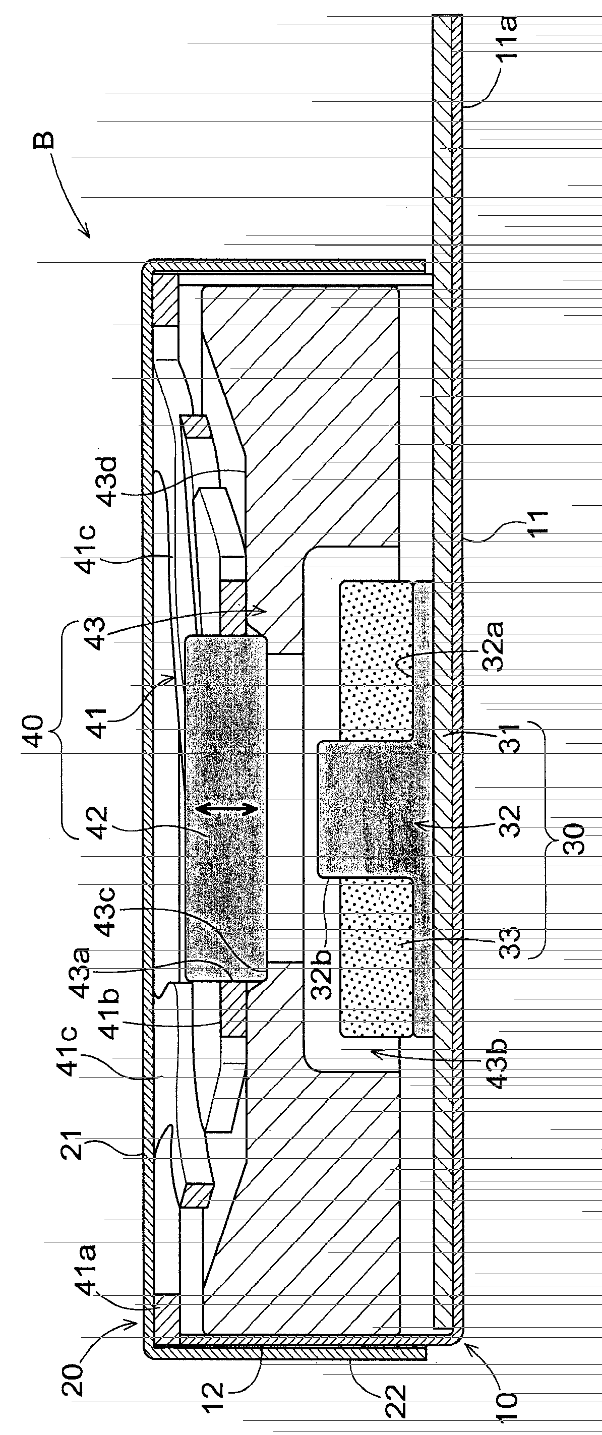
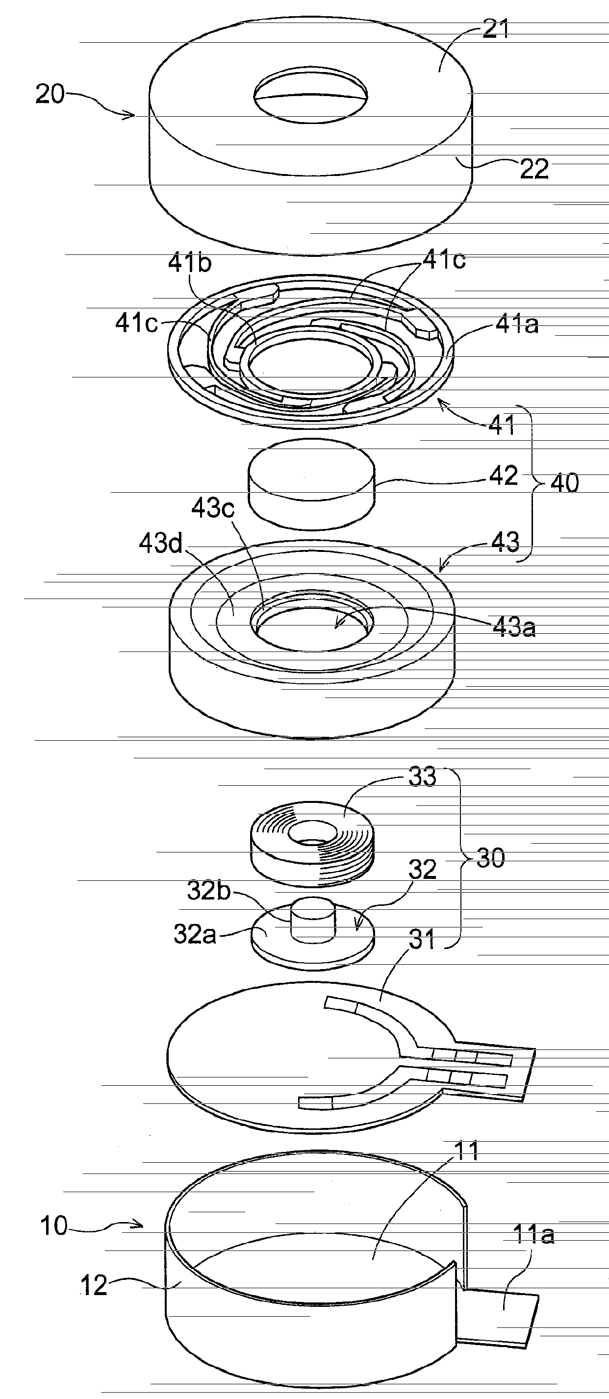
[0023] Below, according to accompanying drawing, describe the embodiment of vibrator of the present invention. figure 1 , figure 2 It is an exploded perspective view and a sectional view of the vibrator in this embodiment. As shown in the figure, in the vibrator B, an electromagnetic circuit 30 and a vibrating body 40 are housed inside a housing formed of the first case 10 and the second case 20 .

[0024] [case]

[0025] The first housing 10 includes a disc-shaped first bottom plate 11 and a first side wall 12 erected from the first bottom plate 11 . In this embodiment, the first side wall 12 is not provided on the entire circumference of the first bottom plate 11 , but is configured as a part of an opening, and the extension portion 11 a extends from the first bottom plate 11 through the opening.

[0026] On the other hand, the second housing 20 includes: a disc-shaped second base plate 21 having a diameter slightly larger than the diameter of the first base plate 11 of ...

Embodiment 2

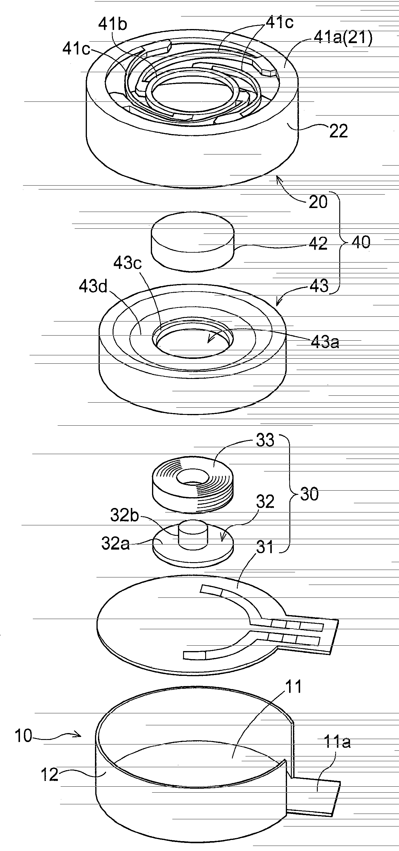
[0045] image 3 is an exploded perspective view of the vibrator in this embodiment. The vibrator in the present embodiment differs from the vibrator in the first embodiment in that the second case 20 and the support body 41 are integrally formed. In addition, the same symbols are attached to the same components as in the first embodiment, and detailed description thereof will be omitted here.

[0046] As shown in the figure, the second bottom plate 21 of the second housing 20 of this embodiment is formed with a circular opening. Furthermore, the circumference of the second bottom plate 21 is integrally assembled with the support arm 41c of the support body 41 . That is, in this embodiment, the second bottom plate 21 constitutes the first ring 41 a of the support body 41 , and the first ring 41 a is integrally formed with the second housing 20 .

[0047] In this way, by integrating the first ring 41 a of the support body 41 and the second case 20 , the number of parts and th...


PUM


Abstract

A vibrator B includes a substrate 31, a coil 33 supported to the substrate 31 and a vibrator member 40 disposed in opposition to the coil 33 and capable of vibrating along the axial direction of the coil 33. The vibrator member 40 includes a weight 43, a magnet 42 polarized along the axial direction of the coil 33, and a supporting member 41 for supporting the magnet 42 with allowing displacement thereof along the axial direction of the coil 33.

Description

technical field [0001] This invention relates to vibrators that convert electrical signals into vibrations. Background technique [0002] In recent years, vibrators that convert electrical signals into vibrations have been used in various devices. For example, a mobile phone or the like has a function of notifying the user of an incoming call by vibrating instead of ringing. Portable game machines and game machine controllers have a function of providing vibration according to the game situation in order to enhance the sense of reality. In addition, it is also applied to a purpose of providing a tactile sensation when a user touches the panel by being incorporated into a touch panel. [0003] This type of vibrator is, for example, fixing the coil to the frame, and elastically supporting the frame by the magnetic circuit part through the suspension, and disposing the coil in the magnetic gap constituting a part of the magnetic circuit. There is a heavy object in the magneti...

Claims


Application Information

Patent Timeline
Patent Type & Authority Applications(China)
IPC IPC(8): B06B1/04
CPCH02K33/16B06B1/045G04C3/102G04C3/107H02K33/00H02K33/02
Inventor 石原健太郎粟村龙二本永秀典中西贤介
Owner HOSIDEN CORP
Why Eureka
Try Eureka