A Simple Stamping Die for U-shaped Bending Parts

A technology for bending parts and stamping dies, which is applied in the field of simple stamping dies for U-shaped bending parts, and can solve the problems that the parts cannot be demolded smoothly.

Inactive Publication Date: 2016-02-03
朱敏忠
View PDF6 Cites 0 Cited by
  • Summary
  • Abstract
  • Description
  • Claims
  • Application Information

AI Technical Summary

Problems solved by technology

[0003] The purpose of the present invention is to provide a simple stamping die for U-shaped bending parts. The rubber is placed under the base plate of the lower die, which solves the problem that the parts cannot be demoulded smoothly during the bending process, and the upper die and the lower die will not be stuck. Dead, the upper and lower molds of the mold will not be misaligned, thus avoiding the generation of stretch marks and wrinkling of the standing edge when the part is bent

Method used


Image

  • A Simple Stamping Die for U-shaped Bending Parts
  • A Simple Stamping Die for U-shaped Bending Parts
  • A Simple Stamping Die for U-shaped Bending Parts

Examples


Embodiment 1

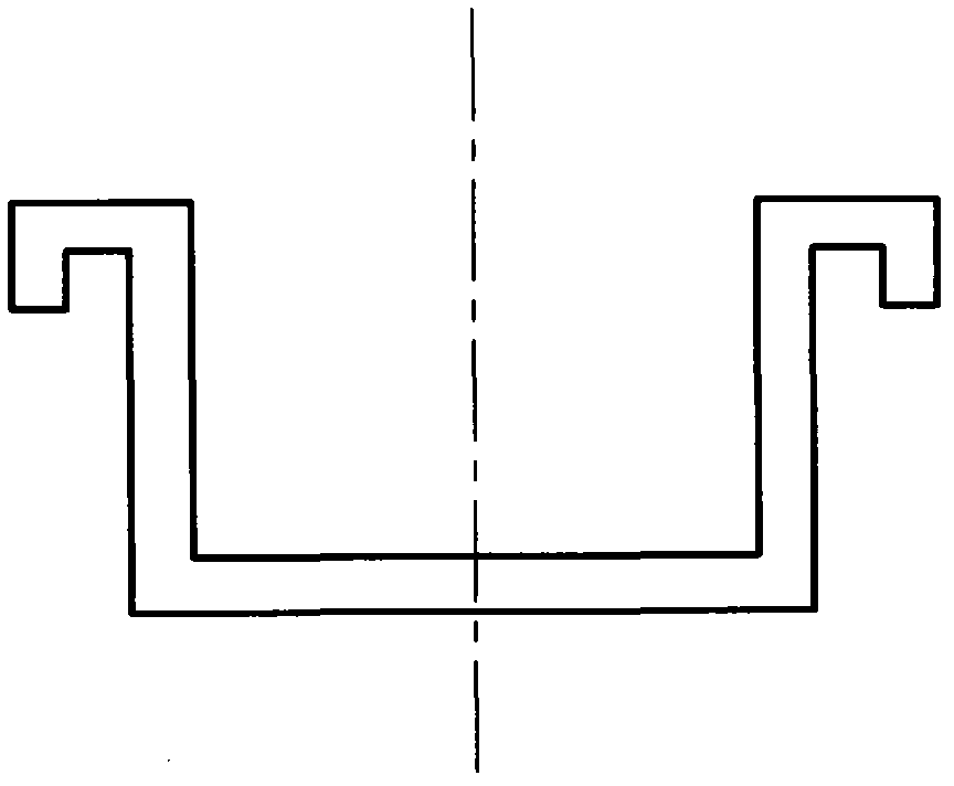
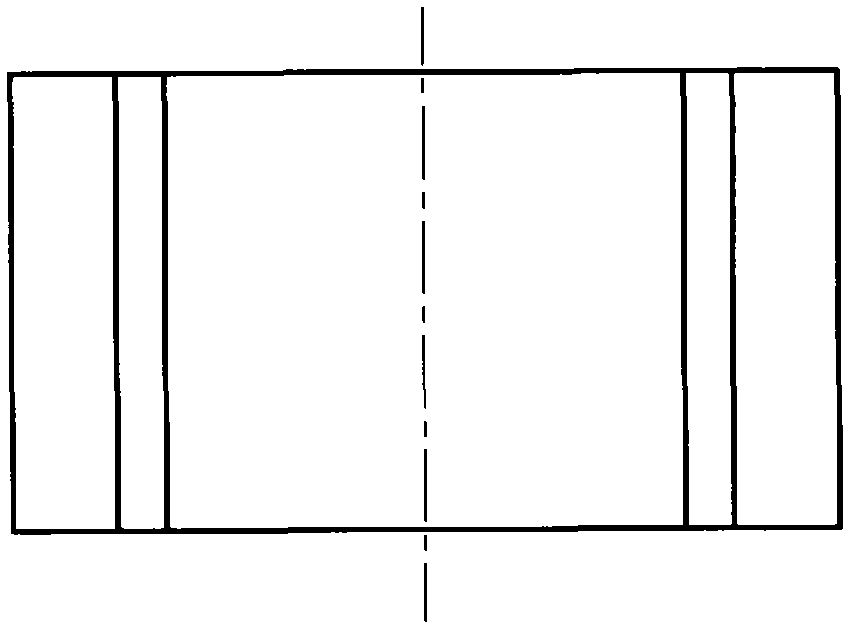
[0022] Embodiment 1, taking the drawing plate part as an example, the simple stamping die will be described in detail.

[0023] A simple stamping die for U-shaped bending parts, consisting of an upper die base 1, a first screw 2, a die handle 3, a stop pin 4, a first pin 5, a guide sleeve 6, a backing plate 7, a guide post 8, and a punch fixing plate 9. Positioning plate 10, second screw 11, die 12, lower mold base 13, second pin 14, third screw 15, upper backing plate 16, rubber 17, fourth screw 18, lower backing plate 19, ejector rod 20. The fifth screw 21, the punch 22, and the top plate; the upper mold base 1 is provided with a mold handle 3, and the mold handle 3 is inlaid in the middle of the upper mold base 1. The material of the upper mold base 1 is HT200. A backing plate 7 is arranged below the die base 1, and a punch fixing plate 9 is arranged below the backing plate 7. The backing plate 7 of the upper die base 1 and the punch fixing plate 9 are provided with threade...


PUM


Abstract

The invention aims to provide a simple U-shaped bending piece stamping mould and belongs to the technical field of stamping moulds. By means of arranging rubber below a lower mould base, the problem that parts cannot be demoulded smoothly in a bending process, an upper mould and a lower mould cannot be clamped, and the upper mould and the lower mould of the stamping mould cannot be displaced. The simple U-shaped bending piece stamping mould comprises an upper mould base (1), screws (2), a mould shank (3), a stop pin (4), a pin (5), a guide sleeve (6), a cushion plate (7), a guide column (8), a male mould fixing plate (9), a positioning plate (10), screws (11), a female mould (12), the lower mould base (13), a pin (14), a screw (15), an upper cushion plate (17), the rubber (17), screws (18), a lower cushion plate (19), an ejection rod (20), screws (21), a male mould (22) and an ejection plate (23). The simple U-shaped bending piece stamping mould is basically free from maintenance, simple to operate, practical and reliable, and acts with cooperation of a special punch press.

Description

technical field [0001] The invention belongs to the technical field of stamping dies, in particular to a simple stamping die for U-shaped bending parts. Background technique [0002] The forming method of parts in which metal materials are bent into certain shapes and angles is called part bending. Bending is a process widely used in stamping production. It can be used to manufacture large structural parts, such as aircraft wings, automobile beams, etc., and can also be used for For the production of small and medium-sized machines and electronic instrument parts, such as hinges, electronic components, etc., there are various bending methods according to the different requirements of the bending parts and the size of the production fingers. The most commonly used method is bending with a bending die on a general-purpose press. In addition, there are also bending, rolling, and stretch bending performed on bending machines, roll bending machines, and stretch bending machines. ...

Claims


Application Information

Patent Timeline
Patent Type & Authority Patents(China)
IPC IPC(8): B21D37/10B21D45/04B21D22/06
Inventor 朱敏忠
Owner 朱敏忠
Why Eureka
Try Eureka