Optical anti-fake element and products utilizing same

An optical anti-counterfeiting and component technology, applied in the field of anti-counterfeiting, can solve the problems of complex process flow, low process controllability and high manufacturing difficulty, and achieve the effects of simple process flow, good process controllability and low manufacturing difficulty

Active Publication Date: 2013-10-23
ZHONGCHAO SPECIAL SECURITY TECH +1
View PDF15 Cites 38 Cited by
  • Summary
  • Abstract
  • Description
  • Claims
  • Application Information

AI Technical Summary

Problems solved by technology

The defect of the anti-counterfeiting element of this structure is: (1) the structure requires that the microlens array and the micro-text array are arranged periodically, and the periodic error is at sub-micron level when making the original plate, so the production difficulty is high; (2) In the production process, the two surfaces of the substrate need to be processed separately in turn, so the process flow is complicated; (3) in the production process, it is necessary to solve the alignment problem of the microlens array and the micro-text array, so the process can be (4) Due to the

Method used


Image

  • Optical anti-fake element and products utilizing same
  • Optical anti-fake element and products utilizing same
  • Optical anti-fake element and products utilizing same

Examples


Embodiment Construction

[0014] The optical anti-counterfeiting element according to the present invention and products using the optical anti-counterfeiting element will be described in detail below in conjunction with the accompanying drawings, so as to better understand the idea of ​​the present invention. It should be understood that the drawings and detailed description are only descriptions of preferred embodiments of the invention and are not intended to limit the scope of the invention in any way.

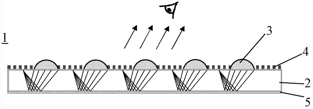
[0015] like figure 1 As shown, the optical security element 1 according to the present invention includes a substrate 2, a micro-relief structure located on the first surface of the substrate 2 and at least partially covering the first surface of the substrate 2, and a micro-relief structure located on the substrate 2. A reflective layer 5 on the second surface of the substrate 2 and at least partially covering the second surface of the substrate 2, wherein the micro-relief structure includes a mic...


PUM


Abstract

The invention aims to overcome defects that in prior art, the optical anti-counterfeiting element is difficult in production, complicated in process and low in process control and strict alignment of the micro graphics array and the micro lens array can't be guaranteed during the production, and provides an optical anti-counterfeiting element and products utilizing the same. The optical anti-fake element comprises base material, a micro relief structure which is arranged on a first surface of the base material and at least partially covers the first surface of the base material, and a reflecting layer which is arranged on a second surface of the base material and at least partially covers the second surface of the base material. The micro relief structure comprises a micro lens array and a micro graphics array which is embedded in the micro lens array and is in the same plane with the micro lens array but is not overlapped with the micro lens array. The micro lens array is capable of sampling and synthesizing the micro graphics array through the reflecting layer so as to produce represented images.

Description

technical field [0001] The present invention relates to the field of anti-counterfeiting, in particular to an optical anti-counterfeiting element suitable for various high security products and high value-added products such as banknotes, credit cards, passports and securities, and also to products using the optical anti-counterfeiting element, such as banknotes, Credit cards, passports and securities, etc. Background technique [0002] Due to its unique visual effect and easy identification, optical anti-counterfeiting components are widely used in high-security products such as banknotes, credit cards, passports and securities, as well as other high-value-added products. [0003] Patent documents such as CN101563640, CN101443692, CN101120139, CN101346244, US5712731, US0034082, US4765656, US4892336, CN1271106, CN1552589 and other patent documents disclose the same type of anti-counterfeiting elements with microlens arrays and micrographic arrays on the two surfaces of the s...

Claims


Application Information

Patent Timeline
IPC IPC(8): B44F1/12G02B3/00
Inventor 张宝利朱军李成垚王晓利
Owner ZHONGCHAO SPECIAL SECURITY TECH
Why Eureka
Try Eureka