Paddy field operation machine

A technology for working machines and paddy fields, applied in agriculture, transplanting machinery, planting methods, etc., can solve the problems of high cost, decreased durability of the front wheel differential mechanism, complicated structure of the front wheel differential mechanism, etc. Durability, miniaturization, simplification and miniaturization effects

Active Publication Date: 2013-10-23
KUBOTA LTD
View PDF6 Cites 3 Cited by
  • Summary
  • Abstract
  • Description
  • Claims
  • Application Information

AI Technical Summary

Problems solved by technology

As a result, the structure of the front wheel differential mechanism (differential case) becomes complicated and large, and there are concerns about a decrease in durability and an increase in cost of the front wheel differential mechanism.

Method used


Image

  • Paddy field operation machine
  • Paddy field operation machine
  • Paddy field operation machine

Examples


Embodiment approach

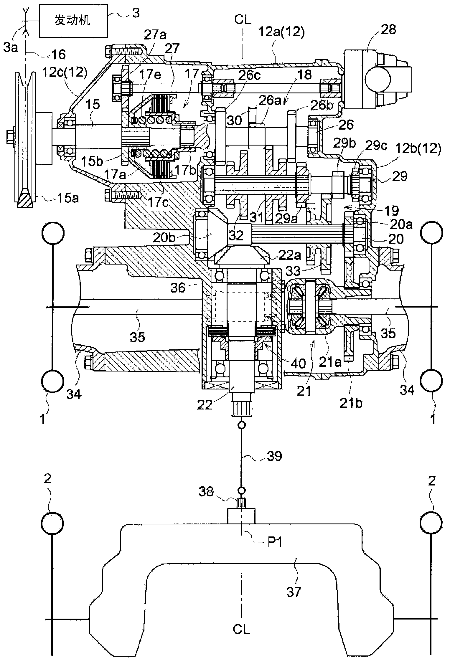
[0179] In the above "specific implementation method" image 3 In the case, the support box part 12c and the input shaft 15 of the gearbox 12 may be provided on the right side of the body with respect to the main body part 12a of the gearbox (the left and right center CL of the body), and the cover part 12b of the gearbox 12 and the front shaft may be provided on the left side of the body. Wheel differential mechanism 21 (spur gear 21b).

[0180] With such a configuration, the spur gear 20a of the travel transmission shaft 20 and the spur gear 21b of the front wheel differential mechanism 21 are provided on the left side of the body with the front wheel differential mechanism 21 interposed therebetween in plan view. The bevel gear 20b of the travel transmission shaft 20, the bevel gear 22a of the rear wheel drive shaft 22, and the rear wheel drive shaft 22 are arranged on the right side of the body through the front wheel differential mechanism 21 in a plan view, and the rear w...


PUM


Abstract

A paddy field operation machine. A front part of a machine body has transmissions (18, 19) for driving, a driving transmission shaft (20) that transmits power from the transmissions (18, 19) for driving, and a front wheel differential mechanism (21) that transmits power to a right front wheel and a left front wheel (1). Power of the driving transmission shaft (20) is transmitted to the front wheel differential mechanism (21) by means of first transmission mechanisms (20a, 21b). A rear wheel transmission shaft (22) that transmits power to a right rear wheel and a left rear wheel (2) is arranged, and power of the driving transmission shaft (20) is transmitted to the rear wheel transmission shaft (22) by means of second transmission mechanisms (20b, 22a). The abovementioned paddy field operation machine can realize improvement of durability of the front wheel differential mechanism and low cost.

Description

technical field [0001] The present invention relates to a structure of a driving transmission system that transmits power to front wheels and rear wheels in paddy field work machines such as a passenger-type rice transplanter and a passenger-type direct seeding machine, and a power transmission system that transmits power to paddy field work equipment included in the machine body Construction of the transmission system. Background technique [0002] The structure disclosed in patent document 1 exists in the riding-type rice transplanter which is an example of a paddy field working machine. [0003] In Patent Document 1, a traveling transmission and a front wheel differential mechanism that transmits power to the right and left front wheels are provided at the front of the body, and the power of the traveling transmission is transmitted via spur gears. For the front wheel differential mechanism (differential case). It is also configured to have a rear wheel propeller shaft ...

Claims


Application Information

Patent Timeline
Patent Type & Authority Applications(China)
IPC IPC(8): B60K17/16B60K17/08
CPCA01C11/02B60K17/06B60K17/28
Inventor 儿岛祥之
Owner KUBOTA LTD
Why Eureka
Try Eureka