
Optical axis adjustment mechanism of vehicle headlamp

A technology for headlights and structure adjustment, which is applied to vehicle components, optical signals, lighting devices, etc., can solve the problems of increasing the number of parts, increasing the manufacturing cost, difficulty in manufacturing and maintenance, etc., so as to simplify the optical axis adjustment structure and reduce manufacturing costs. Cost and effect of reducing the number of parts

Inactive Publication Date: 2015-11-18
HONDA MOTOR CO LTD
View PDF6 Cites 0 Cited by
  • Summary
  • Abstract
  • Description
  • Claims
  • Application Information

AI Technical Summary

Problems solved by technology

[0003] However, in the technology described in Japanese Patent Application Laid-Open No. 2001-319507, it is configured as follows: each headlamp is connected with a unique alignment shaft, and the interlocking mechanism is engaged with the unique alignment shaft, thereby Any one of the inherent alignment axes can adjust the alignment of a plurality of headlights, therefore, multiple inherent alignment axes and the linkage mechanism are required, and the adjustment mechanism needs to be connected with each other. Engaging drive gears, therefore, increased part count and higher manufacturing costs
In addition, the structure of the alignment adjustment may be complicated, making manufacturing and maintenance difficult

Method used


Image

  • Optical axis adjustment mechanism of vehicle headlamp
  • Optical axis adjustment mechanism of vehicle headlamp
  • Optical axis adjustment mechanism of vehicle headlamp

Examples


Embodiment Construction

[0026] Hereinafter, a preferred embodiment of an optical axis adjustment mechanism for a vehicle headlamp according to the present invention will be described in detail with reference to the drawings.

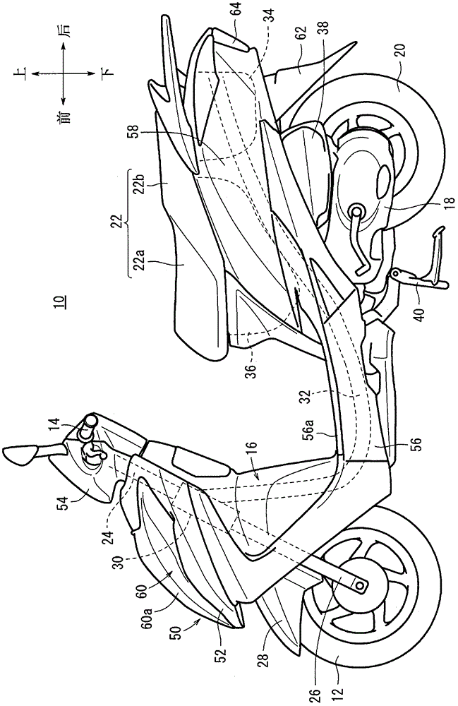
[0027] figure 1 It is a schematic left side view of a scooter-type motorcycle (vehicle) 10 which is a type of saddle-riding vehicle. In this embodiment, the scooter-type motorcycle 10 is taken as an example to describe the present invention, but the present invention is not limited thereto, and of course can be applied to other types of motorcycles (including bicycles with prime movers). In addition, in order to facilitate the understanding of the present invention, unless otherwise indicated, the figure 1 The indicated arrow directions are used as references to describe the front-rear and up-down directions, and the left-right directions will be described in terms of directions seen by a driver seated on the vehicle body.

[0028] Such as figure 1 As shown, a scooter-type m...


PUM


Abstract

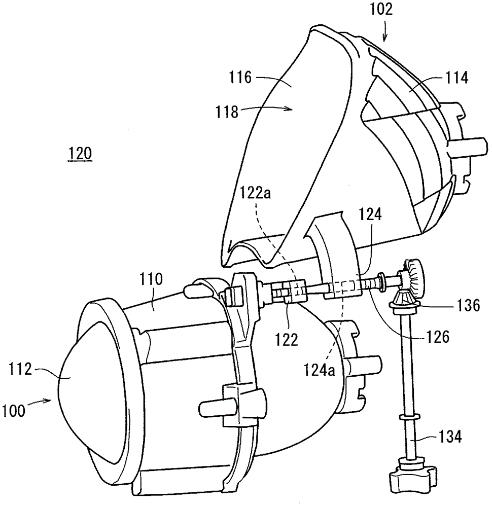
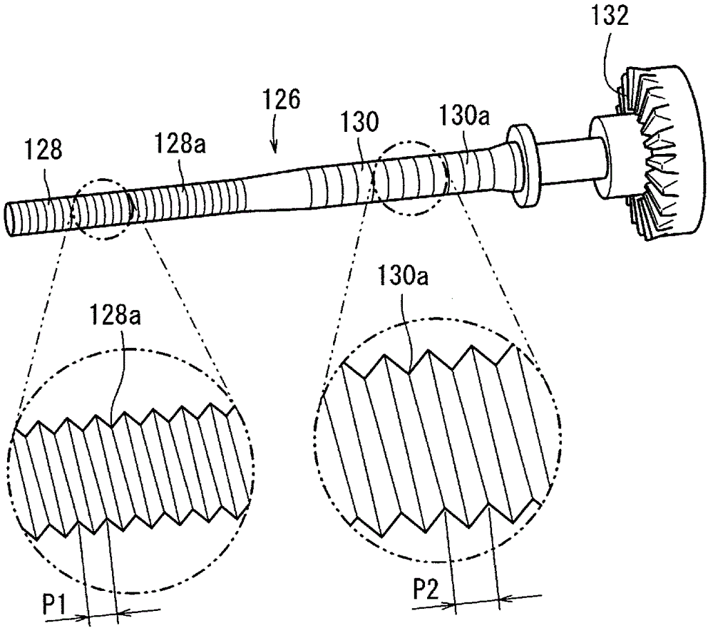
The invention provides an optical axis adjusting mechanism for headlamps of a vehicle. The optical axis adjusting mechanism adjusts optical axes of the multiple headlamps, can reduce the manufacture cost and can be easy to manufacture and maintain. An optical axis adjusting structure (120) for the headlamps of the vehicle (10) comprises a first headlamp (100) provided with a first optical axis adjusting portion (122), a second headlamp (102) provided with a second optical axis adjusting portion (124) and an optical axis adjusting unit (126) for adjusting the first headlamp (100) and the second headlamp (102) by acting the first optical axis adjusting portion (122) and the second optical axis adjusting portion (124), wherein the optical axis adjusting unit (126) is provided with a first adjusting portion (128) and a second adjusting portion (130) which are arranged on the same axis. The first adjusting portion (128) is clamped with the first optical axis adjusting portion (122), and the second adjusting portion (130) is clamped with the second optical axis adjusting portion (124).

Description

technical field [0001] The present invention relates to an optical axis adjustment mechanism of a vehicle headlamp, which adjusts the optical axes of a plurality of headlamps. Background technique [0002] Japanese Patent Application Laid-Open No. 2001-319507 describes a vehicle headlight that performs optical axis adjustment (alignment adjustment) of a plurality of headlights by rotating an alignment shaft. [0003] However, in the technology described in Japanese Patent Application Laid-Open No. 2001-319507, it is configured as follows: each headlamp is connected with a unique alignment shaft, and the interlocking mechanism is engaged with the unique alignment shaft, thereby Any one of the inherent alignment axes can adjust the alignment of a plurality of headlights, therefore, multiple inherent alignment axes and the linkage mechanism are required, and the adjustment mechanism needs to be connected with each other. The meshing drive gears, therefore, increase the number ...

Claims


Application Information

Patent Timeline
Patent Type & Authority Patents(China)
IPC IPC(8): B60Q1/06F21V14/00
Inventor 中竹顺一蔡菊香
Owner HONDA MOTOR CO LTD
Learn More