Supercharge Your Innovation With Domain-Expert AI Agents!

Desuperheater with pressure pushing function

A desuperheater and pressure technology, applied in fluid pressure actuation devices, fluid pressure actuation system components, mechanical equipment, etc., can solve the problem that ball valves cannot be used for high-temperature and high-pressure fluids

Inactive Publication Date: 2013-10-23
郝思宏
View PDF0 Cites 2 Cited by
  • Summary
  • Abstract
  • Description
  • Claims
  • Application Information

AI Technical Summary

Problems solved by technology

[0003] The purpose of the present invention is to solve the problem that the above-mentioned ball valve cannot be used for high-temperature and high-pressure fluids, and to provide a desuperheater with pressure propulsion function installed between the new low-torque non-wear fixed ball valve and the hydraulic system

Method used


Image

  • Desuperheater with pressure pushing function
  • Desuperheater with pressure pushing function
  • Desuperheater with pressure pushing function

Examples


Embodiment Construction

[0017] The present invention will be further described below in conjunction with accompanying drawing and specific embodiment:

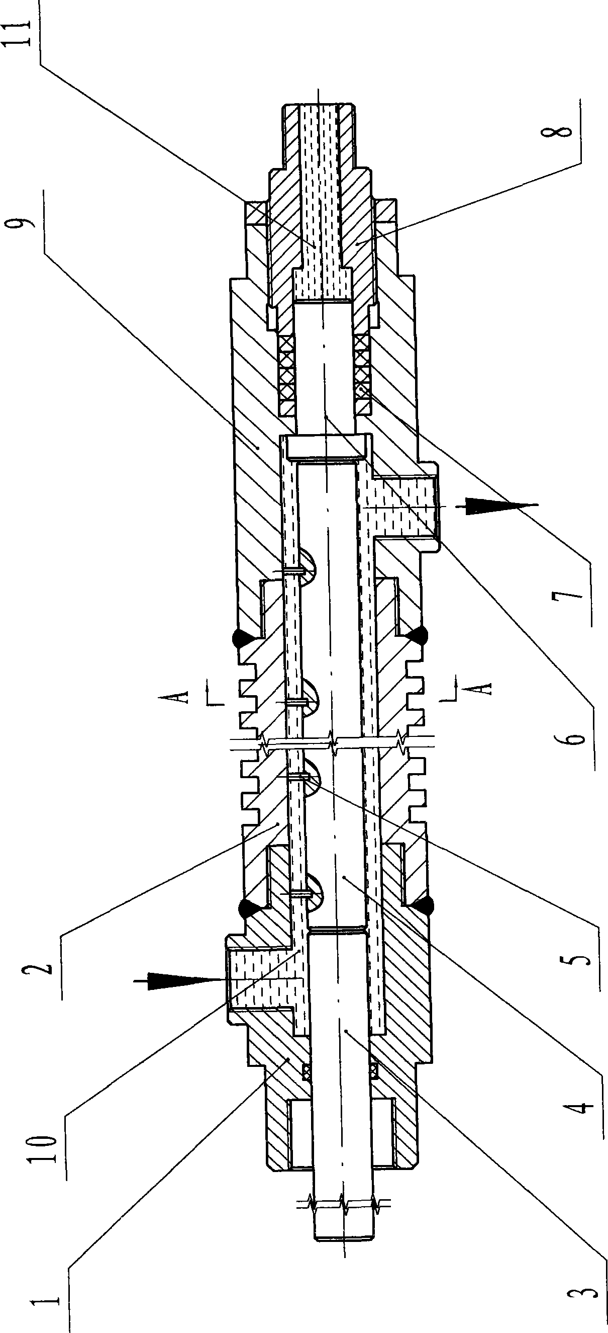
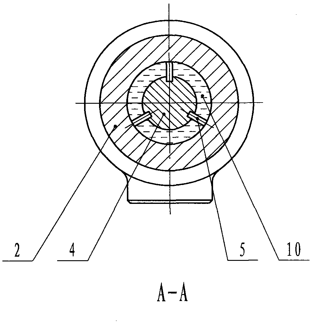
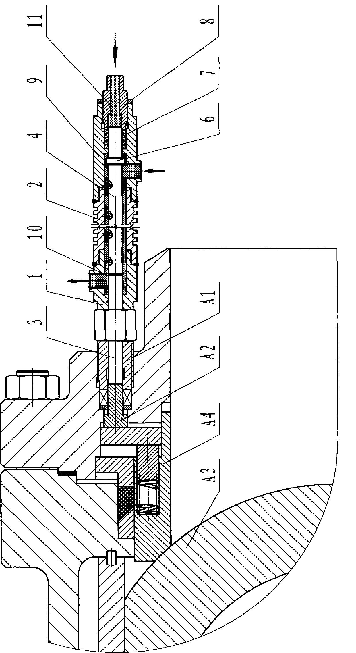
[0018] Such as figure 1 , figure 2 A desuperheater with pressure propulsion function is shown, which includes a joint body 1 with a coolant inlet, and the inner side of the joint body 1 is connected with the threaded sealing ring pressure sleeve A1 in the new low-torque non-wearing fixed ball valve , the outer side is in a sealed connection with the coolant flow tube 2, and the coolant flow tube 3 is in a sealed connection with the main body 9 with a coolant outlet in the pressure propulsion device, forming a coolant inlet and outlet channel between them .

[0019] The pressure propelling device has a main body 9, the inner hole of the main body 9 is equipped with a piston 6, and the piston 6 has a thick round rod part and a thin round rod part, and the thin round rod part is sealed with the seal installed in the main body 9 stepped holes. The in...


PUM


Abstract

The invention discloses a desuperheater with a pressure pushing function. The desuperheater is installed between a novel low-torque non-wear fixed ball valve and a hydraulic system and aims at solving the problem that the ball valve cannot be applied to a high-temperature and high-pressure fluid. The desuperheater comprises a connector body with a cooling liquid inlet, the connector body is in sealing connection with a cooling liquid flowing tube, the cooling liquid flowing tube is in sealing connection with a body, with a cooling liquid outlet, of a pressure pushing device so as to form a cooling liquid inlet and outlet flowing channel, cooling liquid flows in the cooling liquid inlet and outlet flowing channel to take away heat transferred to the desuperheater with the pressure pushing function from the novel low-torque non-wear fixed ball valve used in a high-temperature and high-pressure fluid pipe, and the fact that the hydraulic system can complete operation of pressure transmission and the like in the effective temperature range is guaranteed.

Description

technical field [0001] The invention relates to a desuperheater, in particular to a desuperheater with a pressure propulsion function matched with a novel low-torque non-wearing fixed ball valve and a hydraulic system. Background technique [0002] There is a new type of low-torque and wear-free fixed ball valve. The sealing specific pressure is generated by the pressure of the hydraulic system directly driving the relevant parts on the ball valve, because the viscosity of the liquid in the hydraulic system will become lower as the temperature increases, which will affect the hydraulic pressure. The working stability of the system creates the problem that the ball valve cannot be used for high-temperature and high-pressure fluids. As far as this product is concerned, this is a new problem. The requirement to solve this problem is to ensure that the hydraulic system can effectively complete the pressure transmission within the rated temperature range. Contents of the inventi...

Claims


Application Information

Patent Timeline
Patent Type & Authority Applications(China)
IPC IPC(8): F15B21/04
Inventor 郝思宏
Owner 郝思宏
Features
  • R&D
  • Intellectual Property
  • Life Sciences
  • Materials
  • Tech Scout
  • Unparalleled Data Quality
  • Higher Quality Content
  • 60% Fewer Hallucinations
Learn More