Supercharge Your Innovation With Domain-Expert AI Agents!

Tyre dismounting machine

A technology of tire disassembly and disassembly machine, which is applied in tire installation, tire parts, transportation and packaging, etc. It can solve the problems of overturning heavy tires, slow disassembly work, and low work efficiency, so as to overcome pressure deviation, improve work efficiency, The effect of reducing labor intensity

Inactive Publication Date: 2006-11-22
王育磊
View PDF0 Cites 0 Cited by
  • Summary
  • Abstract
  • Description
  • Claims
  • Application Information

AI Technical Summary

Problems solved by technology

[0002] When a truck tire is deflated, the tire needs to be repaired. At present, the common practice is to use a crowbar to slowly disassemble the work between the tire and the retaining ring. competent
Utilize machine equipment to remove tires, the commonly used structural method is also relatively simple, it is driven by hydraulic pressure to push the placenta structure, its shortcomings are: 1, the edge of the placenta pushed by the tire remover is thick, it is difficult to enter the tire toe and retaining ring In between, the stress point deviates, the toe is easy to deform, and the difficulty of tire removal is increased, and the tire pushing efficiency is low; 2. To remove the retaining ring, it is necessary to manually use a crowbar to pry open the bayonet of the retaining ring, and then use the placenta to pull it out The retaining ring separates the tire from the retaining ring. This method is easy to slip and not easy to pry out the bayonet. The efficiency is relatively low; 3. The tire remover is a single push plate mechanism, and the other side needs to be manually pulled when pushing the tire Push plate seat, the process is cumbersome and takes a long time; 4. There is only one push plate. For the separation of the tire and the retaining ring, when the tire is pushed outward, the tire is easy to slide on the retaining ring, and the work efficiency is low.

Method used


Image

  • Tyre dismounting machine
  • Tyre dismounting machine
  • Tyre dismounting machine

Examples


Embodiment Construction

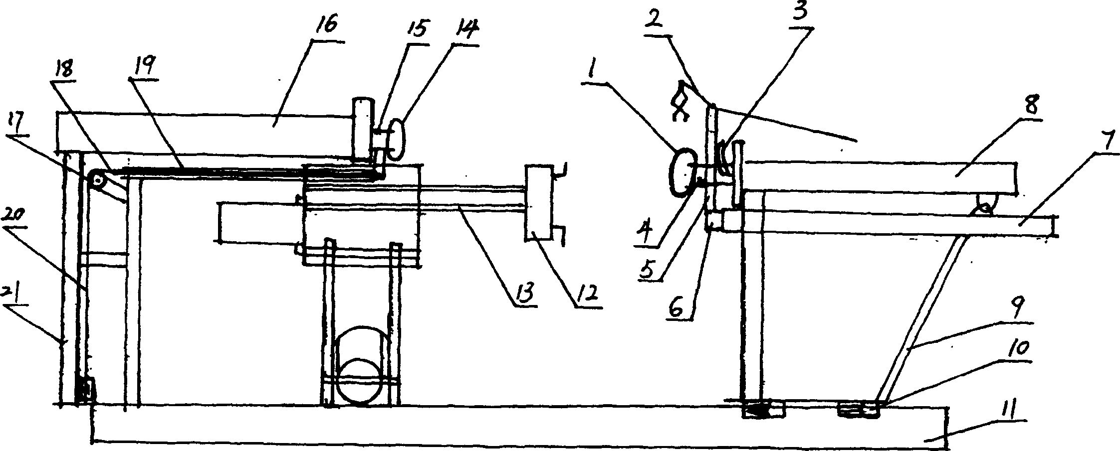
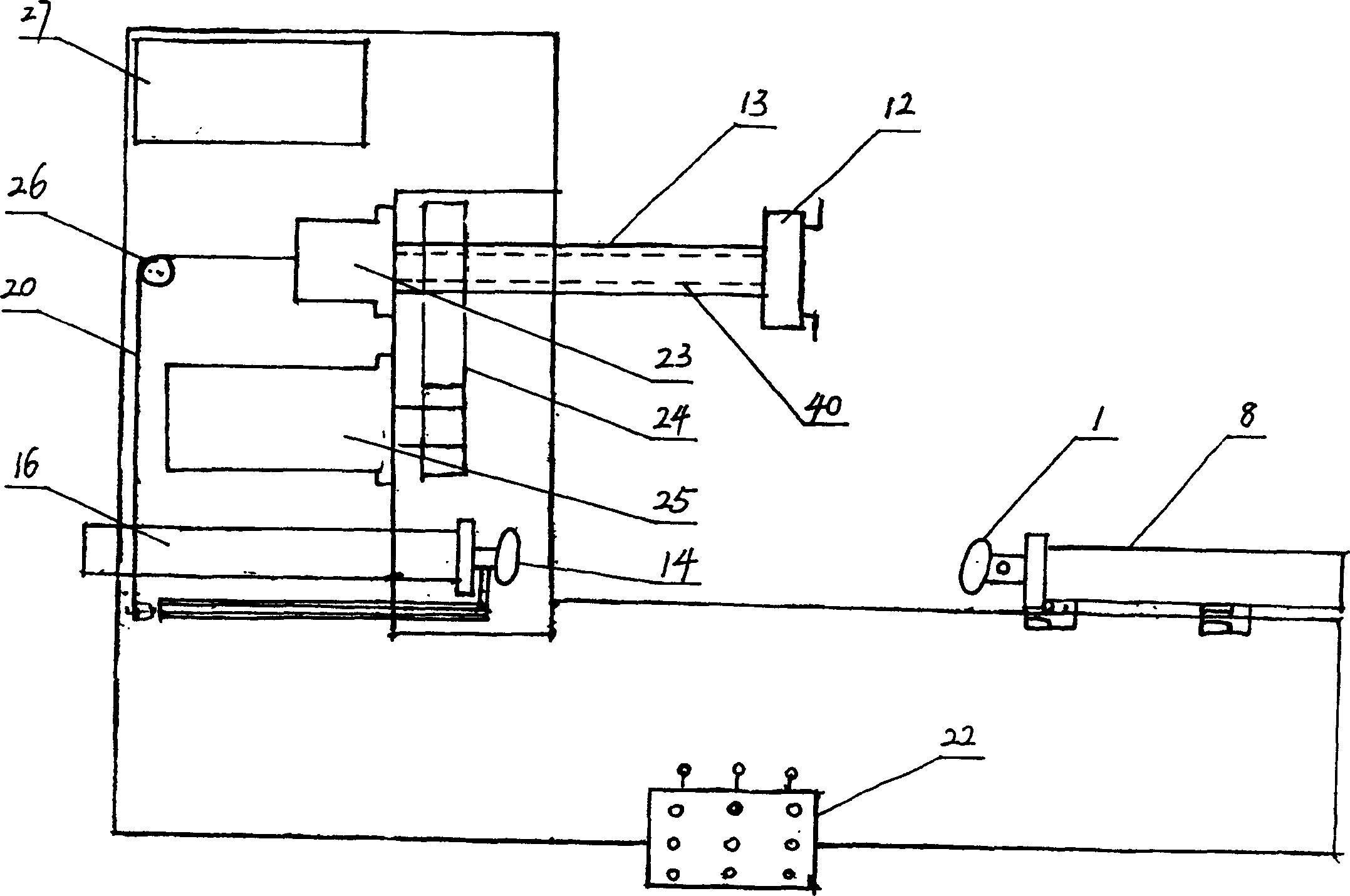
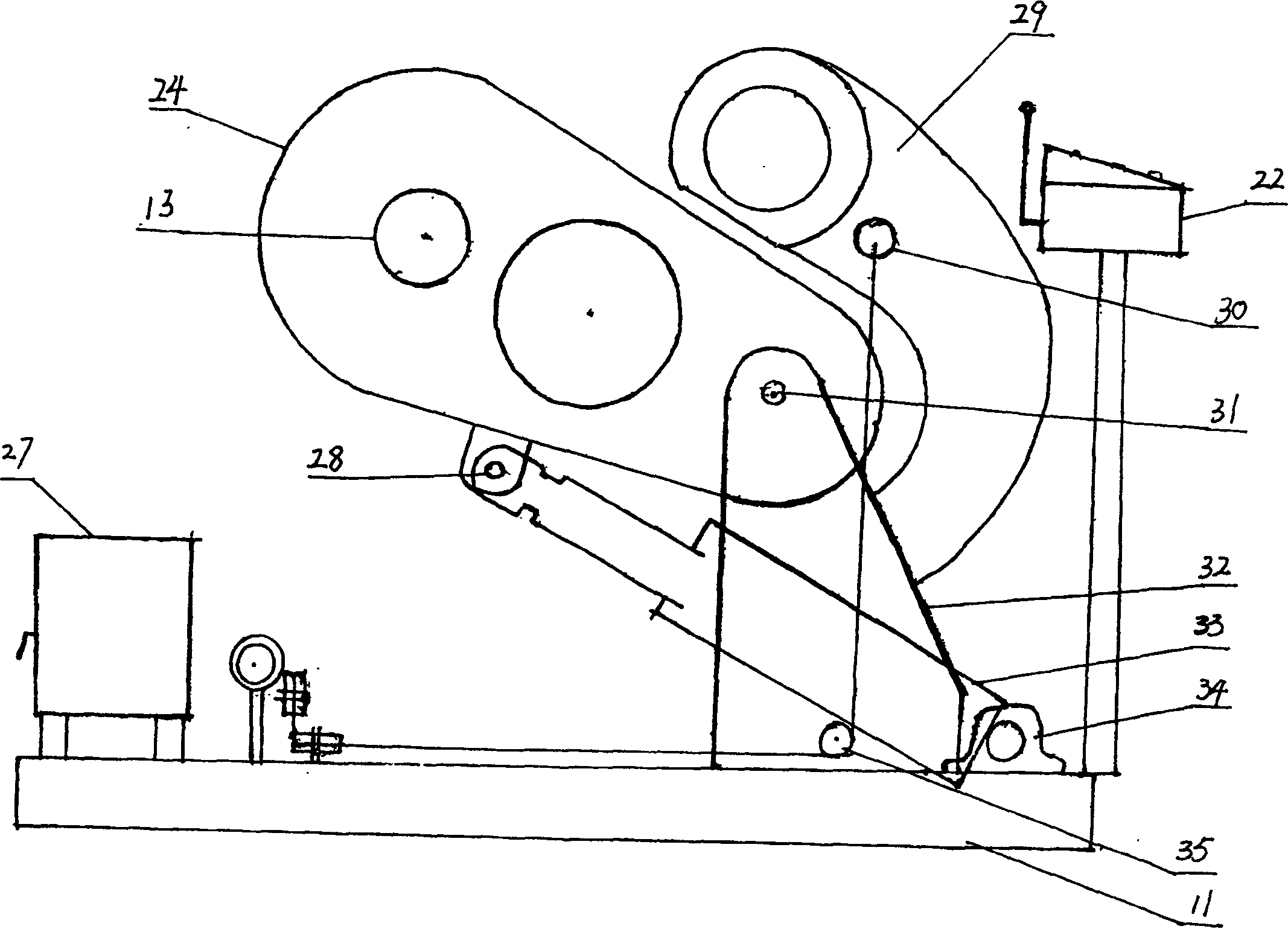
[0030] Figure 1~6 It is a schematic diagram of the structure of an embodiment of the present invention, and the present invention is described below with reference to the accompanying drawings:

[0031] The invention mainly consists of a main tire pushing mechanism, a retaining ring disassembling mechanism, a rear tire pushing mechanism, a rotating mechanism, and a follow-up assist mechanism.

[0032] The main tire pushing mechanism, such as figure 1 , Including the frame 9, the main push placenta 1, the main push tire cylinder 8. The main push placenta 1 is mounted on the main push tire cylinder 8. The front end of the piston rod 4 of the main push tire cylinder 8 is hinged with the piston rod and formed a certain inclination angle, which is convenient for the main push placenta to enter the toe and the retaining ring At the same time, when the tire rotates, the main placenta can rotate with it and reduce friction. The main tire cylinder is installed on the frame 9, and the fra...


PUM


Abstract

A tire dismantling machine includes a base, a main tire pusher mechanism installed on the base, and a retaining ring disassembly mechanism that runs with the main pusher placenta of the main tire pusher mechanism. The front end of the piston rod of the main push tire oil cylinder is hinged with the piston rod, the main push tire oil cylinder is installed on the frame, and the retaining ring dismantling mechanism includes a retaining ring jaw and a jaw opening and closing control mechanism. Opposite to the main tire pushing mechanism, a rear tire pushing mechanism and a follow-up assist mechanism are provided. A rotating mechanism is also provided, including a tire clamping mechanism, a tire rotating mechanism, and a lifting oil cylinder for adjusting the tire. The invention has the advantages of simple structure, convenient operation, reduced labor intensity, high work efficiency, time saving and labor saving.

Description

Technical field [0001] The invention belongs to a repair facility for a truck, and relates to a tire removal machine. Background technique [0002] When the truck tires are flat, the tires need to be repaired. At present, the common practice is to use a lever to slowly disassemble the tires and the retaining ring. This requires considerable effort, and the heavy tires need to be turned over, which is not something ordinary people can do. competent. The commonly used structure method for tire removal using machinery and equipment is relatively simple. It is a placenta structure driven by hydraulic pressure. Its disadvantages are: 1. The tyre changer pushes the placenta with thick edges and it is difficult to enter the toe and retaining ring of the tire. In the meantime, the stress point is deviated, the toe is easy to deform, and it is more difficult to remove the tire, and the tire pushing efficiency is low; 2. To remove the retaining ring, you must first ...

Claims


Application Information

Patent Timeline
Patent Type & Authority Patents(China)
IPC IPC(8): B60C25/132
Inventor 王育强王育磊
Owner 王育磊
Features
  • R&D
  • Intellectual Property
  • Life Sciences
  • Materials
  • Tech Scout
  • Unparalleled Data Quality
  • Higher Quality Content
  • 60% Fewer Hallucinations
Learn More