Supercharge Your Innovation With Domain-Expert AI Agents!

Sealing structure with favorable safety for piston cylinder

A sealing structure, piston cylinder technology, applied in the direction of the engine seal, piston, piston ring, etc., can solve the problems of reducing the service life of the sealing ring, sudden changes in movement speed, safety accidents, etc., to prolong the service life, avoid wear, and ensure Safe to use

Inactive Publication Date: 2015-05-13
皇甫岳伟
View PDF6 Cites 0 Cited by
  • Summary
  • Abstract
  • Description
  • Claims
  • Application Information

AI Technical Summary

Problems solved by technology

[0003] However, in the actual working process, the pressure source cannot always be kept under the control of the ideal value, and the pressure medium entering the inner cavity of the cylinder will fluctuate more or less during the working process
For small-scale fluctuations, it will not have much impact on the piston cylinder itself and the working state, but for larger fluctuations, the movement speed of the piston will change suddenly, resulting in abnormal wear of the sealing ring, causing abnormal working conditions and even A safety accident occurs, and the service life of the sealing ring is also greatly reduced

Method used


Image

  • Sealing structure with favorable safety for piston cylinder
  • Sealing structure with favorable safety for piston cylinder
  • Sealing structure with favorable safety for piston cylinder

Examples


Embodiment 1

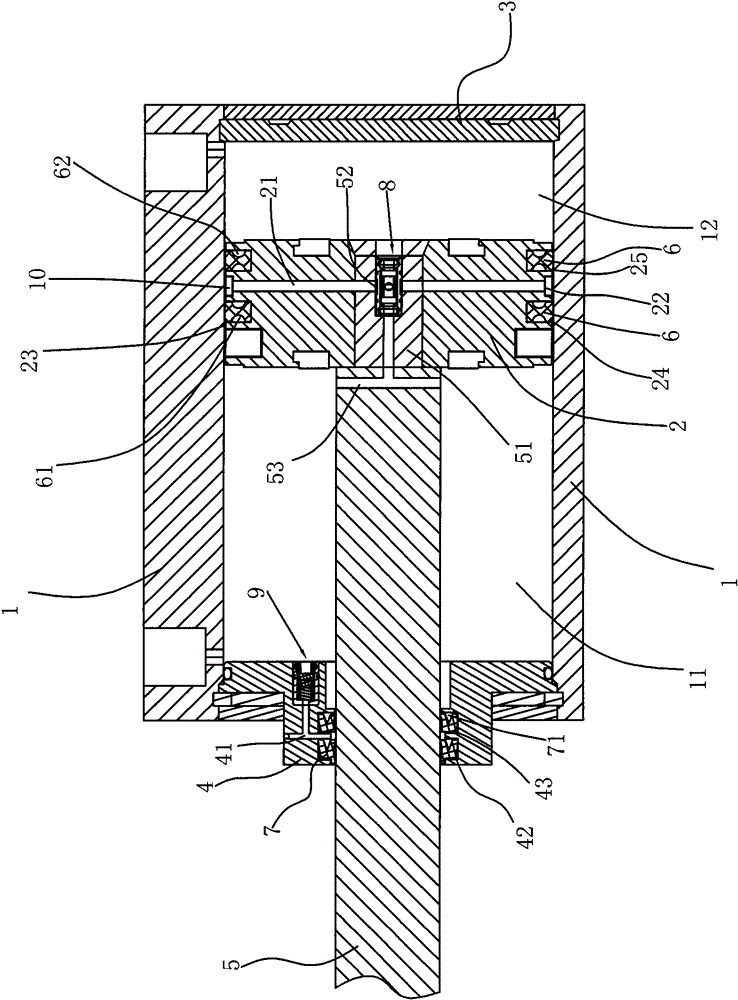
[0033] Such as Figure 1 to Figure 3 As shown, taking the pneumatic cylinder as an example, the safe piston cylinder structure includes:

[0034] The cylinder body 1 is cylindrical, and its inner chamber is divided into a rod chamber 11 and a rodless chamber 12 by a piston 2 described below.

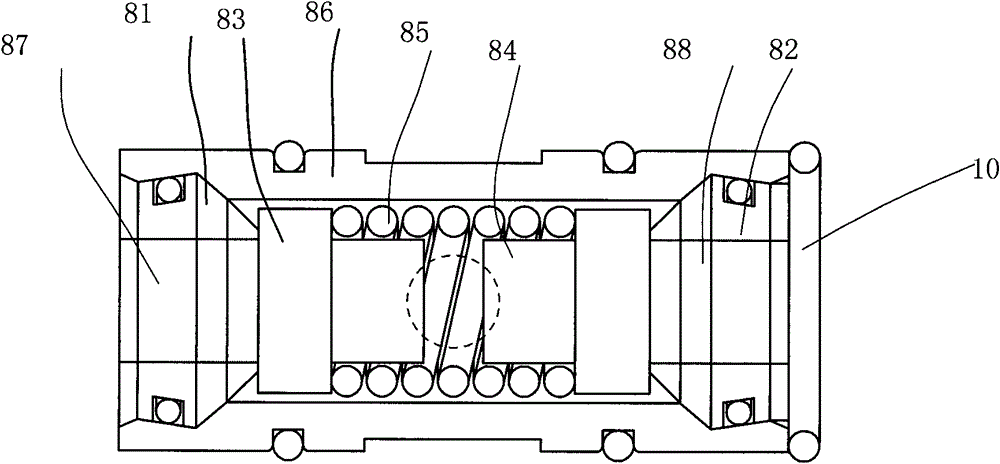
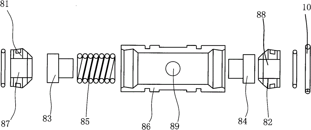
[0035] The piston 2 is movably arranged in the cylinder body 1 , and divides the cylinder body into a rod chamber 11 and a rodless chamber 12 , and there is a small gap 23 between it and the inner wall of the cylinder body 1 . The internal diameter of the piston is provided with a pressure relief hole 21; the peripheral wall of the piston is provided with a circumferential groove 22, and the circumferential groove 22 is provided with a friction block 10 that limits the gap 23 and can lubricate friction, and the circumferential groove 22 is located on the discharge port. Both ends of the pressure hole 21 communicate with the pressure relief hole 21 . On both sides of the circumferential...

Embodiment 2

[0047] Such as figure 2 As shown, the first pressure-sensitive valve in this embodiment is set at the eccentric position of the piston, so that the first pressure-sensitive valve directly communicates with the rodless cavity, and the piston rod does not need to be provided with a piston rod pressure relief channel. This structure can effectively ensure the hardness of the piston rod and increase its service life.

[0048] Other content is identical with embodiment 1.


PUM


Abstract

The invention designs a sealing structure with favorable safety for a piston cylinder, which comprises a cylinder body, a piston, a first end cover, a second end cover, a piston rod and a piston rod sealing ring. The sealing structure is characterized in that a fine clearance is reserved between the piston and the inner wall of the cylinder body; a circumferential groove is arranged on the circumferential wall of the piston; a friction block for limiting the clearance and lubricating the friction is arranged in the circumferential groove; a piston pressure-relief hole is arranged in the piston, wherein the piston pressure-relief hole penetrates through along the diameter direction of the piston and is communicated with the circumferential groove; and a first pressure-sensitive valve is arranged in the axial direction of the piston, wherein the first pressure-sensitive valve is used for communicating a rod cavity with the piston pressure-relief hole and controlling the flowing to be in a one-way direction from the rod cavity to the piston pressure-relief hole and simultaneously communicating a rodless cavity with the piston pressure-relief hole and controlling the flowing to be in a one-way direction from the rodless cavity to the piston pressure-relief hole. Compared with the prior art, the piston cylinder structure provided by the invention is more suitable for work conditions of great pressure fluctuation.

Description

technical field [0001] The invention relates to a cylinder body structure, in particular to a piston-cylinder sealing structure suitable for fluctuation pressure and good safety. Background technique [0002] As we all know, a piston cylinder usually includes a cylinder body, a first end cover and a second end cover arranged at both ends of the cylinder body, a piston arranged in the cylinder body and a piston rod connected to the piston through the first end cover, and the piston connects the cylinder The internal cavity is divided into a rod cavity and a rodless cavity. Since the piston cylinder works by pressure, the sealing performance of the cylinder body and the sealing performance between the rod chamber and the rodless chamber are relatively high. The sealing method adopted is usually to make a groove on the peripheral wall of the piston, and a sealing ring is arranged in the groove, and the sealing between the rod cavity and the rodless cavity is guaranteed by the ...

Claims


Application Information

Patent Timeline
Patent Type & Authority Patents(China)
IPC IPC(8): F16J15/16F16J1/08F16J9/12
Inventor 皇甫岳伟
Owner 皇甫岳伟
Features
  • R&D
  • Intellectual Property
  • Life Sciences
  • Materials
  • Tech Scout
  • Unparalleled Data Quality
  • Higher Quality Content
  • 60% Fewer Hallucinations
Learn More