Lubricating device for power transmission mechanism

A power transmission mechanism and lubricating device technology, applied in the direction of gear lubrication/cooling, etc., can solve the problems of guide tube damage, difficulty in supplying lubricating oil to the position where it should be supplied, guide tube swing, etc., and achieve the effect of improving accuracy and inhibiting damage

Active Publication Date: 2016-01-13
HONDA MOTOR CO LTD
View PDF5 Cites 0 Cited by
  • Summary
  • Abstract
  • Description
  • Claims
  • Application Information

AI Technical Summary

Problems solved by technology

[0005] The technique of arranging a tube in the transmission case in this way and allowing lubricating oil supplied from an oil pump to reach the site to be supplied via the tube is known. Causes the guide pipe to vibrate, and it may be difficult to reliably supply the lubricating oil to the place where it should be supplied
Also, when the guide tube swings, it may cause damage to the guide tube due to contact with the box

Method used


Image

  • Lubricating device for power transmission mechanism
  • Lubricating device for power transmission mechanism
  • Lubricating device for power transmission mechanism

Examples


Embodiment Construction

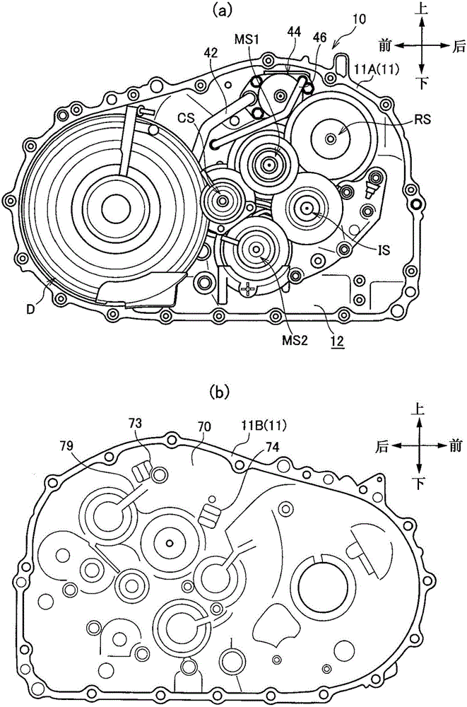
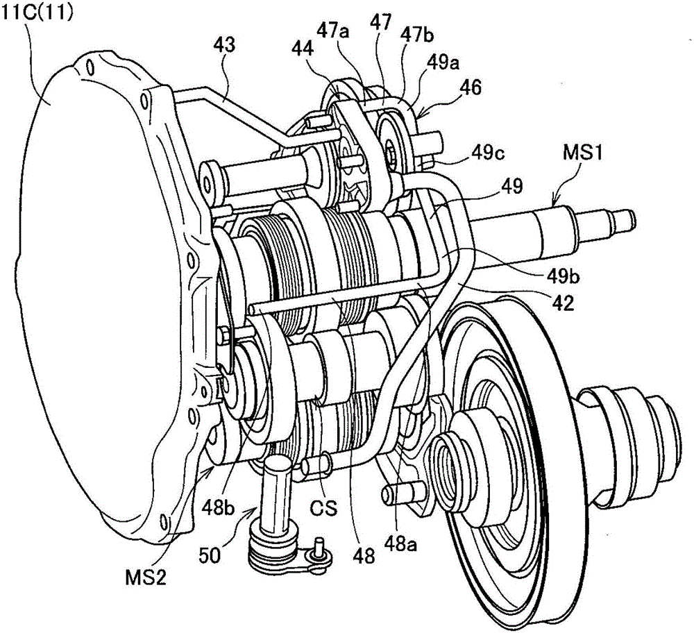
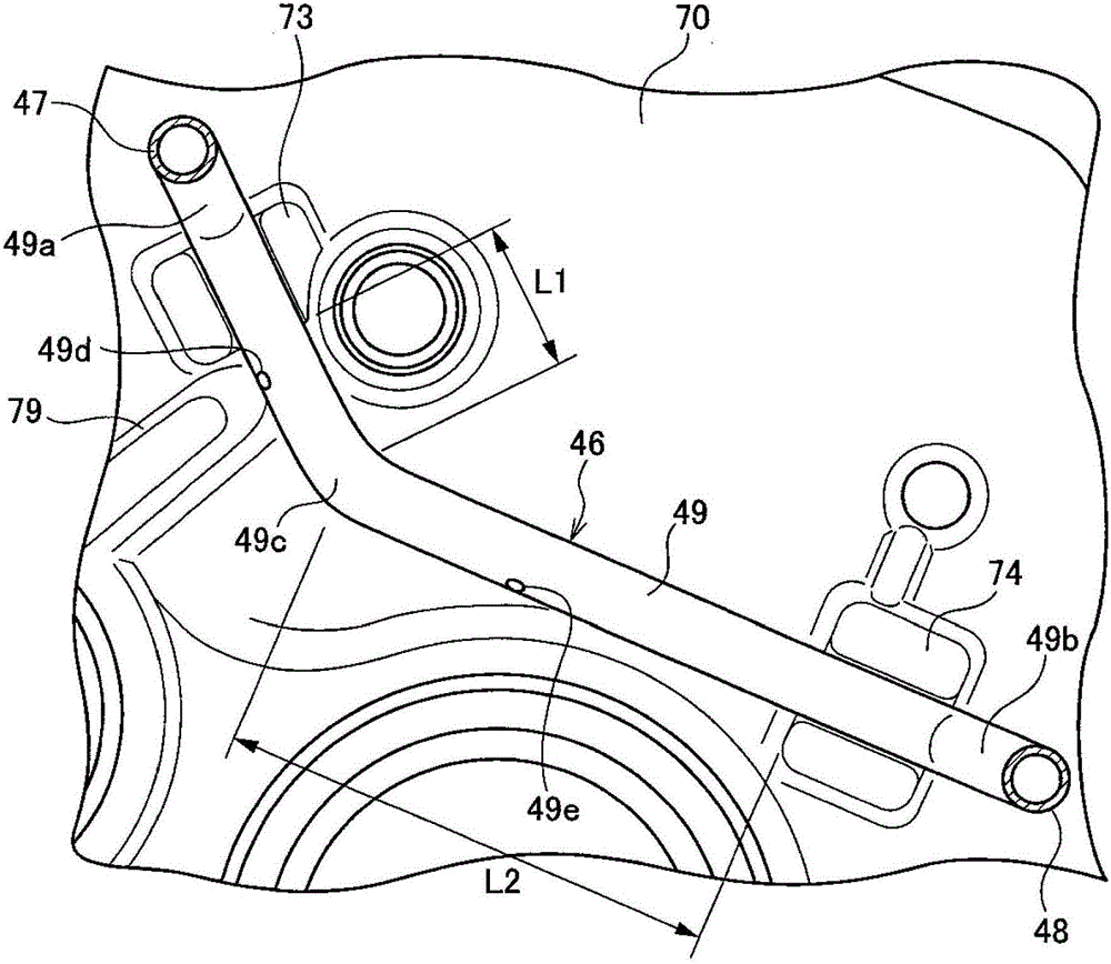
[0047] Below, based on Figure 1 to Figure 5 One embodiment of a lubricating device for a power transmission mechanism (hereinafter referred to as a transmission) of the present invention will be described.

[0048] Such as figure 1 and figure 2 As shown, the transmission 10 for a motor vehicle is provided with a speed change mechanism and a motor not shown in the inside of the transmission case 11 formed by the first case 11A, the second case 11B, and the side cover 11C. The speed change mechanism consists of It is composed of a first main shaft MS1, a second main shaft MS2, an idler shaft IS, an intermediate shaft CS, a reverse shaft RS, and a differential device D whose rotation axes are perpendicular to the plane of the paper. A motor (not shown) is disposed between the transmission mechanism and the side cover 11C so as to be adjacent to the transmission mechanism. and, if figure 1 As indicated by the arrows in , the transmission 10 is arranged so that the vertical d...


PUM


Abstract

The invention provides a lubricating device of a power transmission mechanism. The lubricating device is capable of reliably supplying lubricating oil and preventing the damage of a tube. A third tube position (49) comprises a bending portion (49c) between a first tube position side end portion (49a) and a second tube position side end portion (49b). On the inner surface (70) of a second box body (11B), a first holding portion (73) is formed at the upstream side of the bending portion (49c) and at a position corresponding to the third tube position (49) while a second holding portion (74) is formed at the downstream side of the bending portion (49c) and at a position corresponding to the third tube position (49). An oil hole (49d) for supplying oil for a shaft is disposed at least at the shorter one between distance (L1) and distance (L2), wherein the distance (L1) is between a position, of the third tube position (49), corresponding to the first holding portion (73) and the bending portion (49c), the distance (L2) is between a position, of the of the third tube position (49), corresponding to the second holding portion (74) and the bending portion (49c).

Description

technical field [0001] The present invention relates to a lubricating device for a power transmission mechanism that lubricates gears and the like using an oil pump. Background technique [0002] In the lubricating device described in Patent Document 1, lubricating oil supplied from an oil pump is supplied to the forward / reverse switching device via a guide pipe arranged in the transmission case. [0003] One end of the guide pipe is fixed to the left case housing the forward / backward switching device. The guide pipe extends from the left case to the right case side where the torque converter is housed, and then bends upward, and then from the right side The side of the box body is extended to the left side of the box body. [0004] Patent Document 1: Japanese Patent Laid-Open No. 2000-35109 [0005] The technique of arranging a tube in the transmission case in this way and allowing lubricating oil supplied from an oil pump to reach the site to be supplied via the tube is ...

Claims


Application Information

Patent Timeline
Patent Type & Authority Patents(China)
IPC IPC(8): F16H57/04
Inventor 太田浩司茂木诚一河合则和
Owner HONDA MOTOR CO LTD
Why Eureka
Try Eureka