Supercharge Your Innovation With Domain-Expert AI Agents!

Swirler for combustion chambers

A swirler, fluid technology, applied in the field of burners

Inactive Publication Date: 2013-10-23
GENERAL ELECTRIC CO
View PDF0 Cites 10 Cited by
  • Summary
  • Abstract
  • Description
  • Claims
  • Application Information

AI Technical Summary

Problems solved by technology

Each modification requires a new casting process as well as casting machining

Method used


Image

  • Swirler for combustion chambers
  • Swirler for combustion chambers
  • Swirler for combustion chambers

Examples


Embodiment Construction

[0026] When introducing elements of various embodiments of the invention, "a," "an," "the," and "said" are intended to mean that there are one or more of the elements. The terms "comprising" and "having" are intended to be inclusive and mean that there may be other elements other than the listed elements. Any examples of operating parameters are not meant to exclude other parameters of the disclosed embodiments.

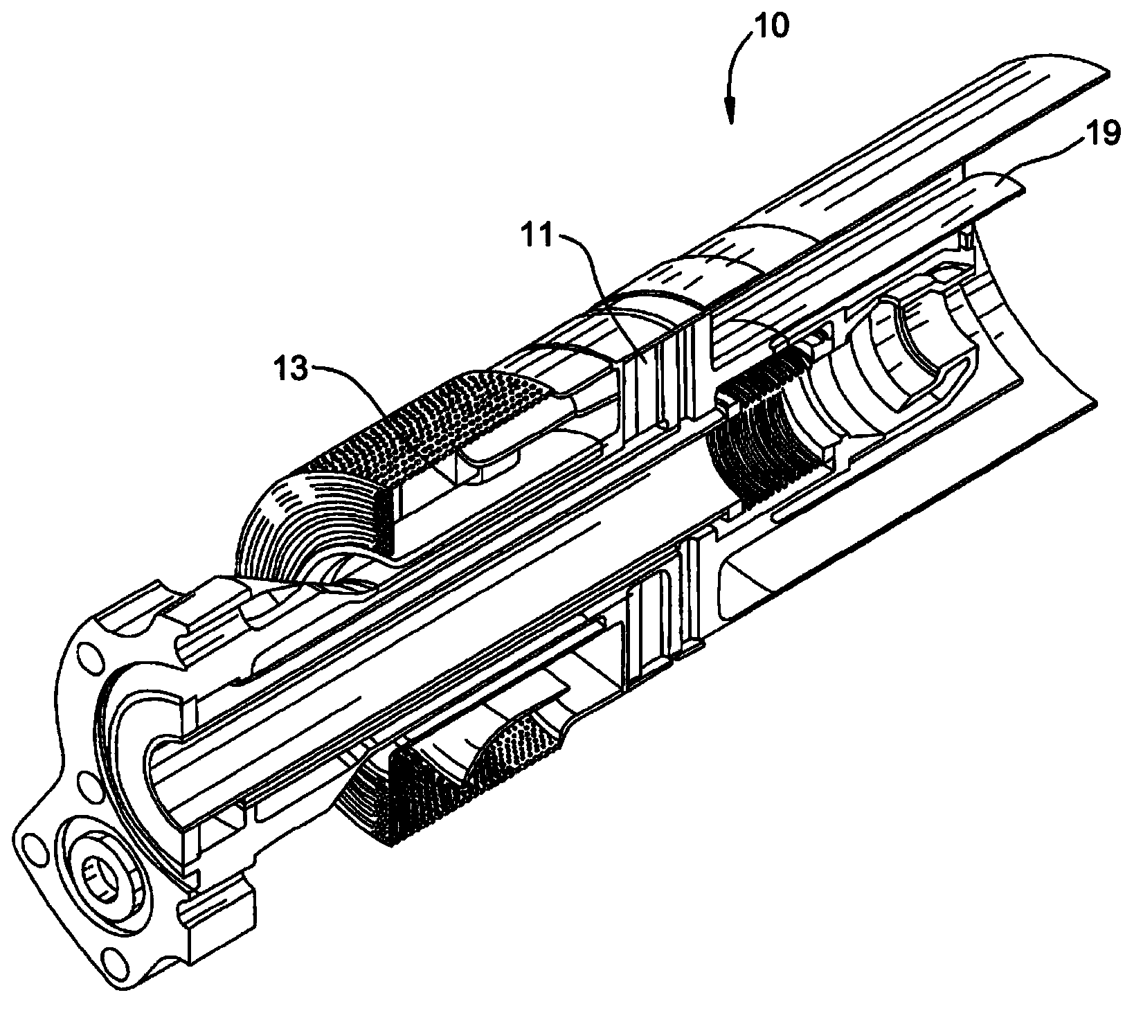
[0027] figure 1 Shown is a portion of a fuel nozzle 10 including a combustion swirler 11 in accordance with an embodiment of the invention. The combustion swirler 11 is configured to receive a flow of combustion fluid, typically air, from a nozzle inlet 13 of the gas turbine and to mix the air with fuel into an air-fuel mixture. The air-fuel mixture then travels downstream for ignition in combustion zone 19 .

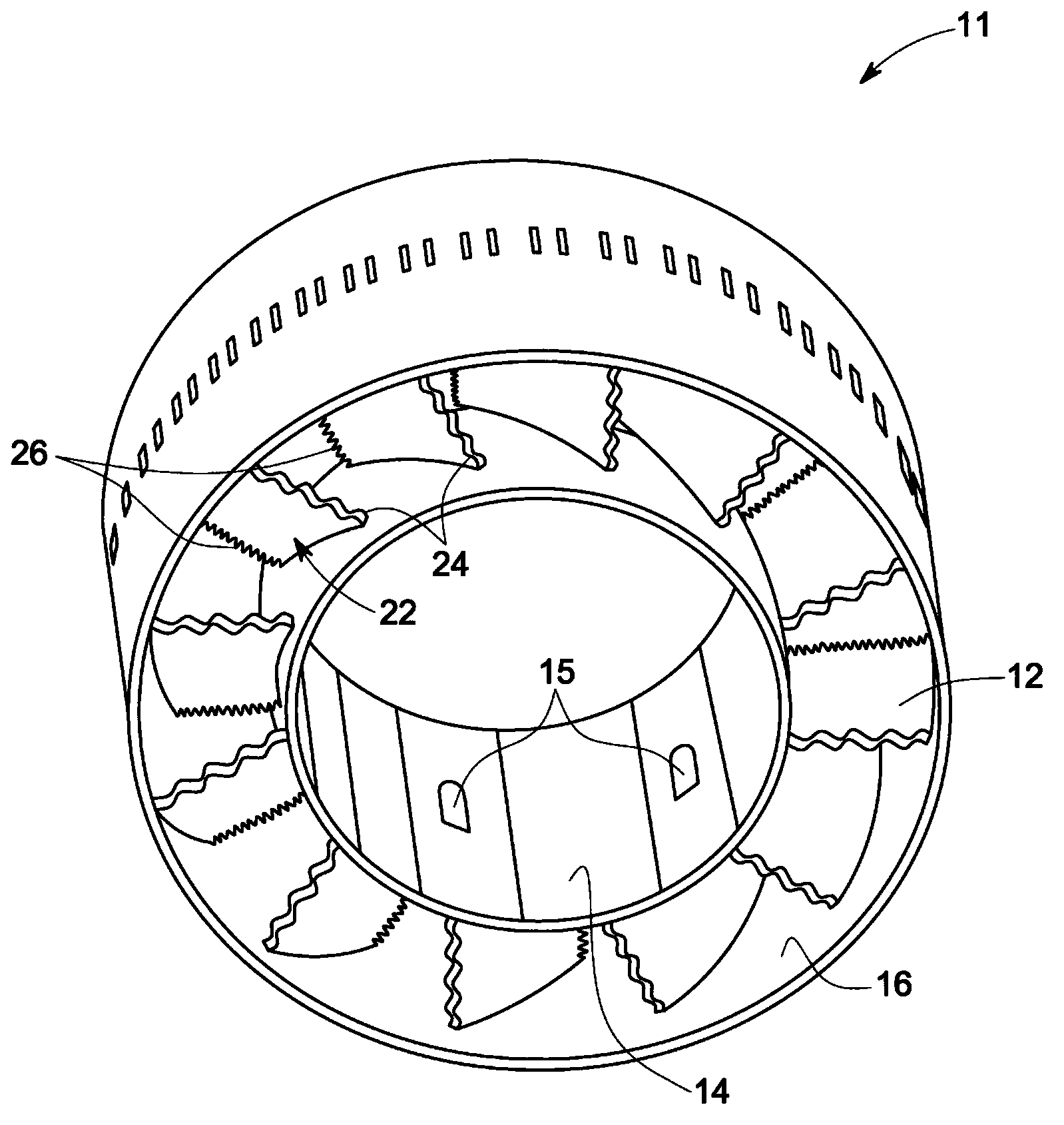
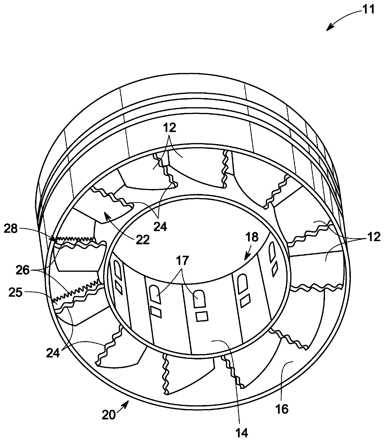
[0028] figure 2 Shown is a perspective view of a combustion swirler 11 according to an embodiment of the invention. As shown, the combustion swirler 11 ...


PUM


Abstract

A combustion swirler (11) is provided. The combustion swirler includes multiple vanes (12) axially extending from an annular first body portion (14) of the combustion swirler. The combustion swirler also includes an annular second body portion (16) enclosing the multiple vanes for directing a flow of combustion fluid. Each of the vanes comprises an aerodynamic blade body comprising a leading edge with a plurality of first tubercles (24) and a trailing edge with a plurality of second tubercles (26).

Description

technical field [0001] This invention relates generally to combustors and, more particularly, to swirlers for combustors. Background technique [0002] Generally, a gas turbine includes a combustor having a swirler, together with fuel nozzles (or swirler nozzles) therein. Each swirler within the nozzle includes one or more channels for delivering the fuel-air mixture (or just air) to the combustion chamber. The swirl fuel nozzle is used to stabilize the flame and improve the mixing of fuel and air prior to ignition. The swirler includes a plurality of vanes extending from the nozzle and having an aerodynamic profile. The swirler vane often includes channels for supplying fuel to fuel holes on the surface of the swirler vane. As the fuel exits the fuel holes, it mixes with the fluid (usually air) flowing over the swirler vanes. Typically, the swirler vanes have a kink near the trailing edge of the swirler vane, which can create flow separation in or downstream of the swir...

Claims


Application Information

Patent Timeline
Patent Type & Authority Applications(China)
IPC IPC(8): F23R3/38
CPCF23R3/14F23R3/286
Inventor B.S.M.阿布德埃尔纳比A.M.埃尔卡迪
Owner GENERAL ELECTRIC CO
Features
  • R&D
  • Intellectual Property
  • Life Sciences
  • Materials
  • Tech Scout
  • Unparalleled Data Quality
  • Higher Quality Content
  • 60% Fewer Hallucinations
Learn More