Decoration strip structure and air conditioner

A technology for decorative strips and air conditioners, applied in decorative arts, instruments, lighting devices, etc., can solve problems such as failure to beautify products, dull surface gloss of decorative strips, etc., to improve competitiveness, improve aesthetic effects, and facilitate popularization and application. Effect

Active Publication Date: 2013-10-23
MIDEA GRP CO LTD
View PDF6 Cites 10 Cited by
  • Summary
  • Abstract
  • Description
  • Claims
  • Application Information

AI Technical Summary

Problems solved by technology

However, since the gloss on the surface of the decorative strip is relatively dull, it cannot bring a good visual effect to the user, thereby failing to play a good role in beautifying the product.

Method used


Image

  • Decoration strip structure and air conditioner
  • Decoration strip structure and air conditioner
  • Decoration strip structure and air conditioner

Examples


Embodiment 1

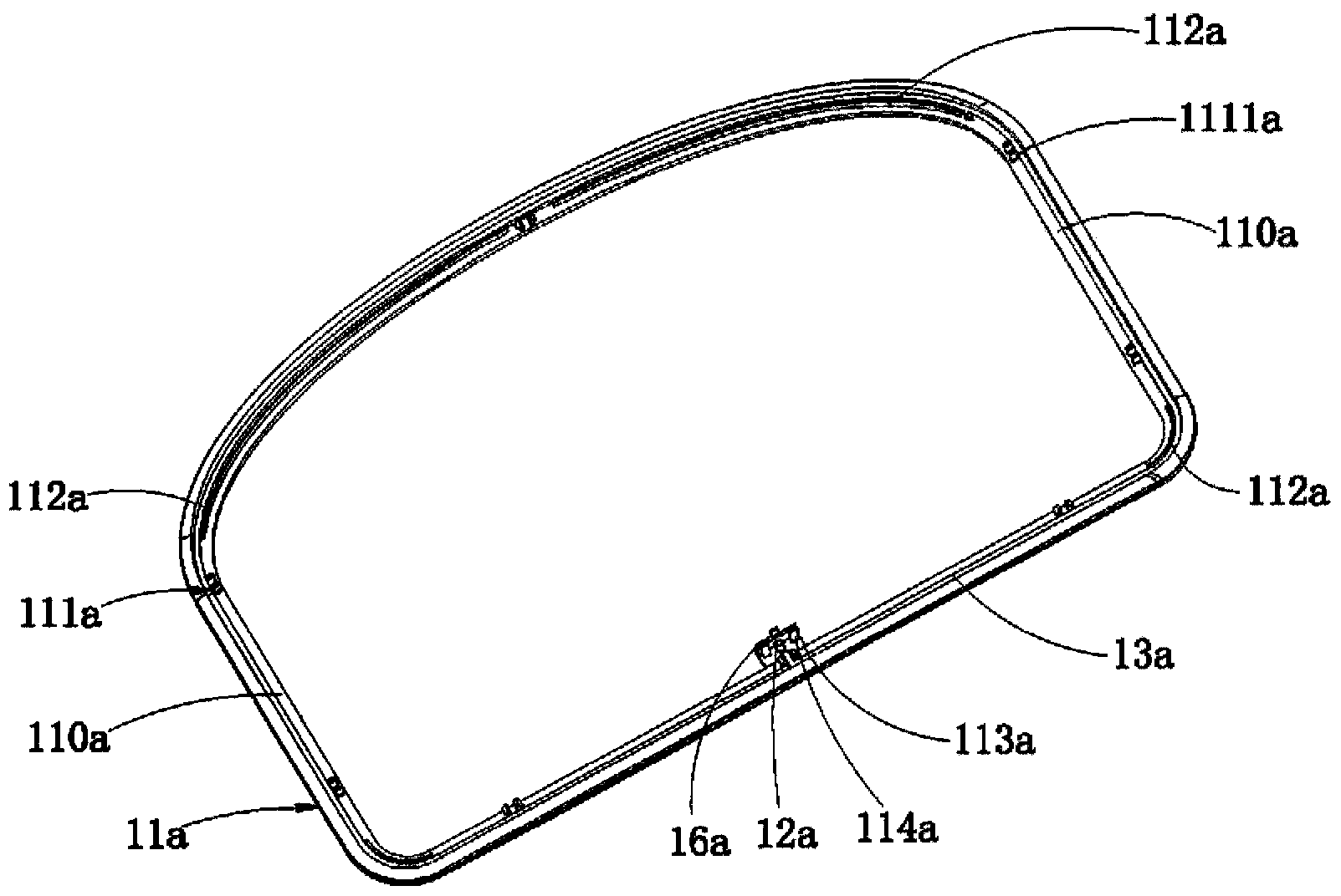
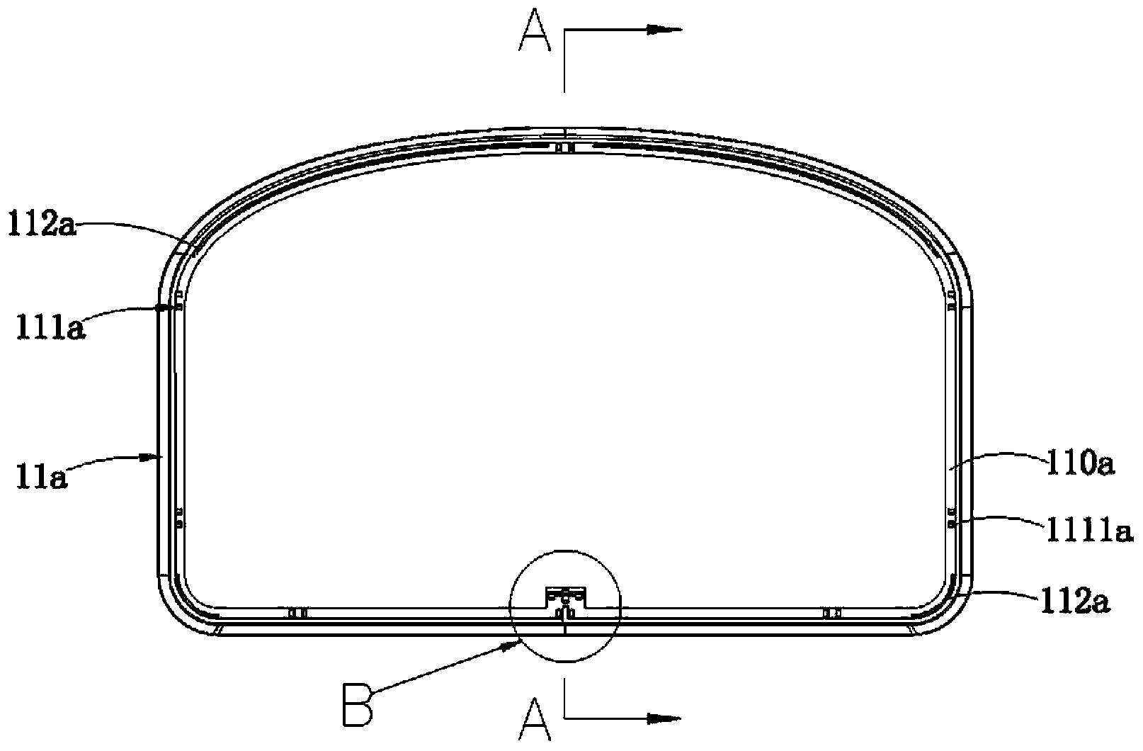
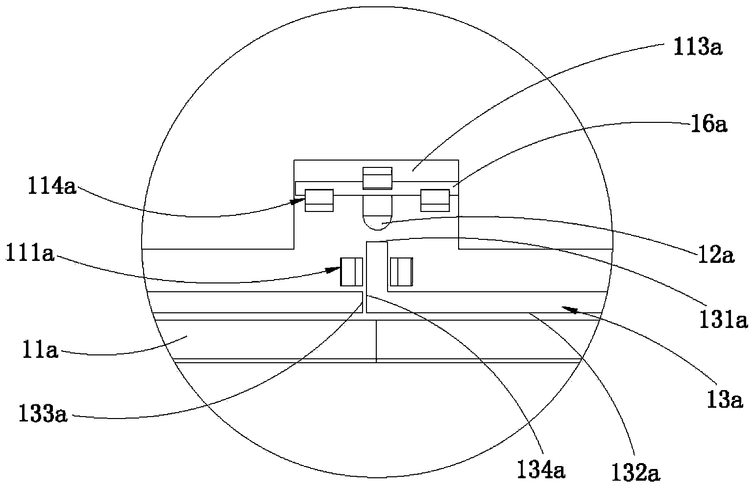
[0037] Such as Figure 1 ~ Figure 4 As shown, in this embodiment, the decorative strip body 11a is a solid light-transmitting member, which is made of a material with good light-transmitting properties, so that almost all the light irradiated on it can pass through it and emit; The inner side of the strip body 11a is dug downward to form a concave edge 110a, that is, the height of the concave edge 110a is smaller than the height of the outer side of the decorative strip body 11a. In specific processing, the decorative strip body 11a can be processed into a solid piece with the same inner and outer heights, and then the concave edge 110a can be processed by digging out a part of the material on the inner top; or the concave edge 110a can be directly molded. At least one set of limiting ribs 112a is provided on the concave edge 110a. The limiting ribs 112a can be integrally formed with the decorative strip body 11a, or can be fixed on the decorative strip body 11a by welding. Th...

Embodiment 2

[0041] Such as Figure 5 ~ Figure 8 As shown, in this embodiment, the decorative strip body 11b is a solid non-transparent member, which is made of a material with poor light transmission, so that the light irradiated on it can hardly pass through it and emit ; The inner side of the decorative strip body 11b is dug downward with a concave edge 110b, and a limiting rib 112b is provided on the concave edge 110b, and the light guide 13b is locked on the concave edge 110b through the limiting rib 112b; it is on the decorative strip body 11b The transparent part 14b is also embedded, and the side of the decorative strip body 11b is correspondingly provided with an embedding groove (not shown in the figure) for the transparent part 14b to be embedded in. The transparent part 14b includes a reflective part protruding from the concave edge 110b 141b, the conductive part 143b inserted in the embedding groove of the decorative strip body 11b and the light emitting part 142b attached to ...

Embodiment 3

[0046] Such as Figure 9 ~ Figure 11As shown, in this embodiment, the decorative strip body 11c is a non-transparent member, and the non-transparent member is made of a material with poor light transmittance, so that the light irradiated on it can hardly pass through it to be emitted; and The decorative strip body 11c is provided as a solid body. Of course, the decorative strip body 11c may also be hollow, and the light guide 13c is pasted on the outside of the decorative strip body 11c. The light guide 13c is bonded and fixed to the outside of the decorative strip body 11c by an adhesive (not shown in the figure), and the inherent viscosity of the adhesive can bond and fix the light guide 13c to the outside of the decorative strip body 11c, so as to The purpose of locking and fixing the light guide member 13c is achieved; and the bonding process is simple to operate and easy to implement, thus facilitating the disassembly and assembly of the light guide member 13c on the deco...


PUM


Abstract

The invention is applicable to the technical field of air conditioner structures, and provides a decoration strip structure. The decoration strip structure comprises a decoration strip body, a light source and a light guide piece arranged on the decoration strip body, wherein the light guide piece is provided with a first incident plane facing towards the light source and a scattering surface facing towards the outer side of the decoration strip body; and the light source injects light into the first incident plane of the light guide piece and emits the light outwards from the scattering surface. With the adoption of the light source and the light guide piece, the light can be emitted outwards from the side part of the decoration strip body, so that a light emitting function of the decoration strip structure is realized, and a visual effect of the decoration strip structure is improved. The invention further provides an air conditioner which comprises a top cap, an air outlet housing and an air inlet housing, wherein the bottom end of the air outlet housing is mounted and fixed at the top of the air inlet housing; the top cap is mounted and fixed at the top end of the air outlet housing; and the decoration strip structures are arranged at the top of the top cap, a matching position between the top cap and the air outlet housing and a matching position between the air outlet housing and the air inlet housing.

Description

technical field [0001] The invention belongs to the technical field of air conditioner structures, in particular to a decorative strip structure and an air conditioner with the decorative structure Background technique [0002] The air conditioner generally includes an air outlet shell, an air inlet shell and a top cover, the top cover is fixed on the top of the air outlet shell, and the bottom of the air outlet shell is fixed on the top of the air inlet shell. On traditional air conditioners, there are often obvious gaps, misalignment and other undesirable phenomena at the joints between the top cover and the air outlet shell, and between the air outlet shell and the air inlet shell, which seriously affect the visual effect of the product. [0003] In order to solve the above problems, in the prior art, it is proposed to add a decorative strip at the position where there are obvious gaps, misalignment and unevenness on the air conditioner, and the decorative strip is subjec...

Claims


Application Information

Patent Timeline
Patent Type & Authority Applications(China)
IPC IPC(8): F24F13/20F21V8/00F21V19/00F21W121/00
Inventor 岑振宙
Owner MIDEA GRP CO LTD
Why Eureka
Try Eureka