Voltage compensation circuit and method of grid electrode driver and liquid-crystal display device

A gate driver, voltage compensation technology, applied in instruments, static indicators, nonlinear optics, etc., can solve the problems affecting display quality, display unevenness, etc., to improve display quality, avoid voltage drop, and solve display unevenness. Effect

Active Publication Date: 2013-10-23
TCL CHINA STAR OPTOELECTRONICS TECH CO LTD
View PDF4 Cites 26 Cited by
  • Summary
  • Abstract
  • Description
  • Claims
  • Application Information

AI Technical Summary

Problems solved by technology

The voltage drop ΔV is likely to cause the phenomenon of display unevenness (mura) on the liquid crystal display panel 13, thereby affecting the display quality

Method used


Image

  • Voltage compensation circuit and method of grid electrode driver and liquid-crystal display device
  • Voltage compensation circuit and method of grid electrode driver and liquid-crystal display device
  • Voltage compensation circuit and method of grid electrode driver and liquid-crystal display device

Examples


Embodiment Construction

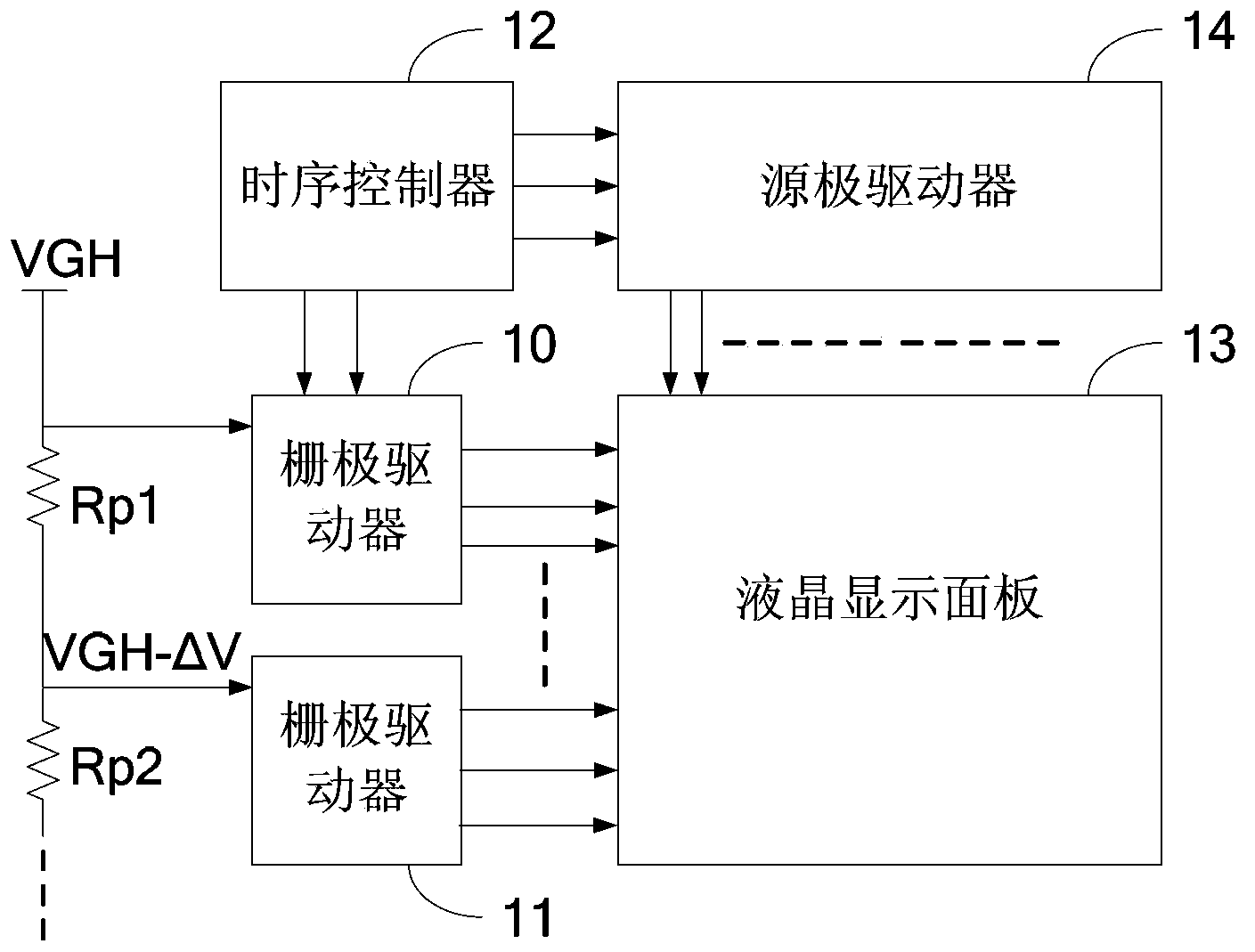
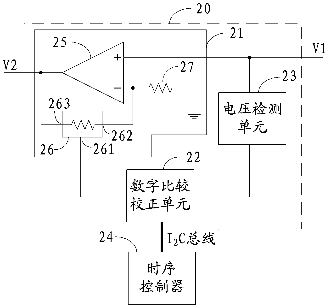
[0020] figure 2 is a schematic structural diagram of the voltage compensation circuit of the gate driver according to the embodiment of the present invention. The voltage compensation circuit is arranged before the output terminal of the gate driver, and is used to adjust the voltage provided by the gate driver to the liquid crystal display panel. Preferably, one voltage compensation circuit is arranged on each gate driver. Such as figure 2 As shown, the voltage compensation circuit 20 of the gate driver of this embodiment includes a voltage adjustment unit 21 , a digital comparison and correction unit 22 and a voltage detection unit 23 .

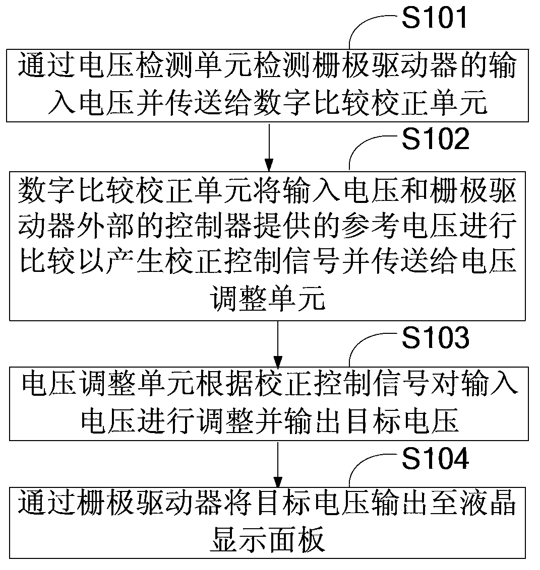
[0021] The voltage detection unit 23 detects the input voltage V1 of the gate driver and sends it to the digital comparison and correction unit 22 . The digital comparison and correction unit 22 also receives the reference voltage provided by the timing controller 24 outside the gate driver, and compares the input voltage V1 with the re...


PUM


Abstract

The invention discloses a voltage compensation circuit and method of a grid electrode driver and a liquid-crystal display device. The voltage compensation circuit comprises a voltage detection unit, a digital comparison correction unit and a voltage adjustment unit. The voltage detection unit detects an input voltage of the grid electrode driver and transmits the input voltage to the digital comparison correction unit. The digital comparison correction unit further receives a reference voltage provided by a controller arranged outside the grid electrode driver and compares the input voltage with the reference voltage so as to generate a correction control signal and transmit the correction control signal to the voltage adjustment unit. The voltage adjustment unit adjusts the input voltage according to the correction control signal and outputs a target voltage. The grid electrode driver outputs the target voltage to a liquid-crystal display panel. According to the mode, a scanning voltage which is transmitted to the grid electrode driver can be adjusted, the voltage drop existing among the output voltages of different grid electrode drivers is avoided, therefore, the display mura phenomenon of the liquid-crystal display panel is solved, and the display quality is improved.

Description

technical field [0001] The invention relates to the technical field of liquid crystal display, in particular to a voltage compensation circuit of a gate driver, a voltage compensation method and a liquid crystal display device. Background technique [0002] Such as figure 1 As shown, in the conventional liquid crystal display device, the timing controller 12 controls the source driver 14 to drive the data lines of the liquid crystal display panel 13 , and controls the gate drivers 10 and 11 to drive the scanning lines of the liquid crystal display panel 13 . Wherein, the VGH voltage is the gate turn-on voltage, which is input to the gate drivers 10 and 11 through wiring, and transmitted to the liquid crystal display panel 13 through the gate drivers 10 and 11 . [0003] The resistors Rp1 and Rp2 are the wire resistances between the gate drivers. When the VGH voltage is transmitted through the wires, due to the voltage loss of the wire resistances, the scanning voltages tran...

Claims


Application Information

Patent Timeline
Patent Type & Authority Applications(China)
IPC IPC(8): G09G3/36
CPCG09G3/3677G09G3/3696G09G2320/0223G02F1/13306
Inventor 张峻恺吴智豪
Owner TCL CHINA STAR OPTOELECTRONICS TECH CO LTD
Why Eureka
Try Eureka