Stereo coding method and device
A stereo and encoding technology, applied in the multimedia field, can solve the problems of inability to achieve realistic restoration, uncomfortable listening experience of the listener, and inability to meet the recovery requirements, and achieve the effect of improving encoding efficiency and enhancing sound field effects.
- Summary
- Abstract
- Description
- Claims
- Application Information
AI Technical Summary
Problems solved by technology
Method used
Image

Examples
Embodiment 1
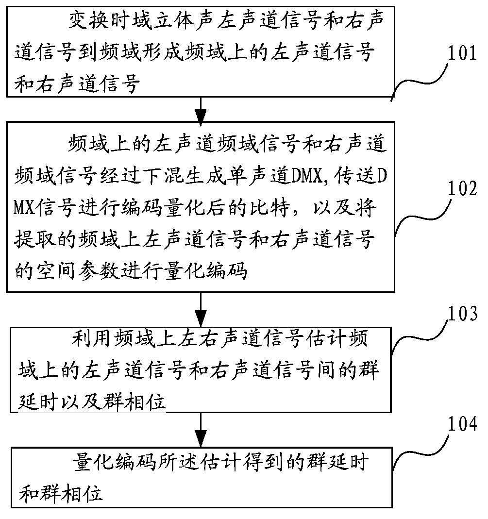
[0032] figure 1 A schematic diagram of the implementation of a stereo coding method, including:
[0033] Step 101: Transform the time domain stereo left channel signal and the right channel signal into the frequency domain to form the left channel signal and the right channel signal in the frequency domain.
[0034] Step 102: The frequency-domain signal of the left channel and the frequency-domain signal of the right channel in the frequency domain are downmixed to generate a mono-channel downmix signal (DMX), and the encoded and quantized bits of the DMX signal are transmitted, and the extracted frequency domain The spatial parameters of the upper left channel signal and the right channel signal are quantized and encoded.
[0035] The spatial parameter is a parameter representing the spatial characteristics of a stereo signal, such as an ILD parameter.
[0036] Step 103: Estimate a group delay (Group Delay) and a group phase (Group Phase) between the left channel signal and...
Embodiment 2
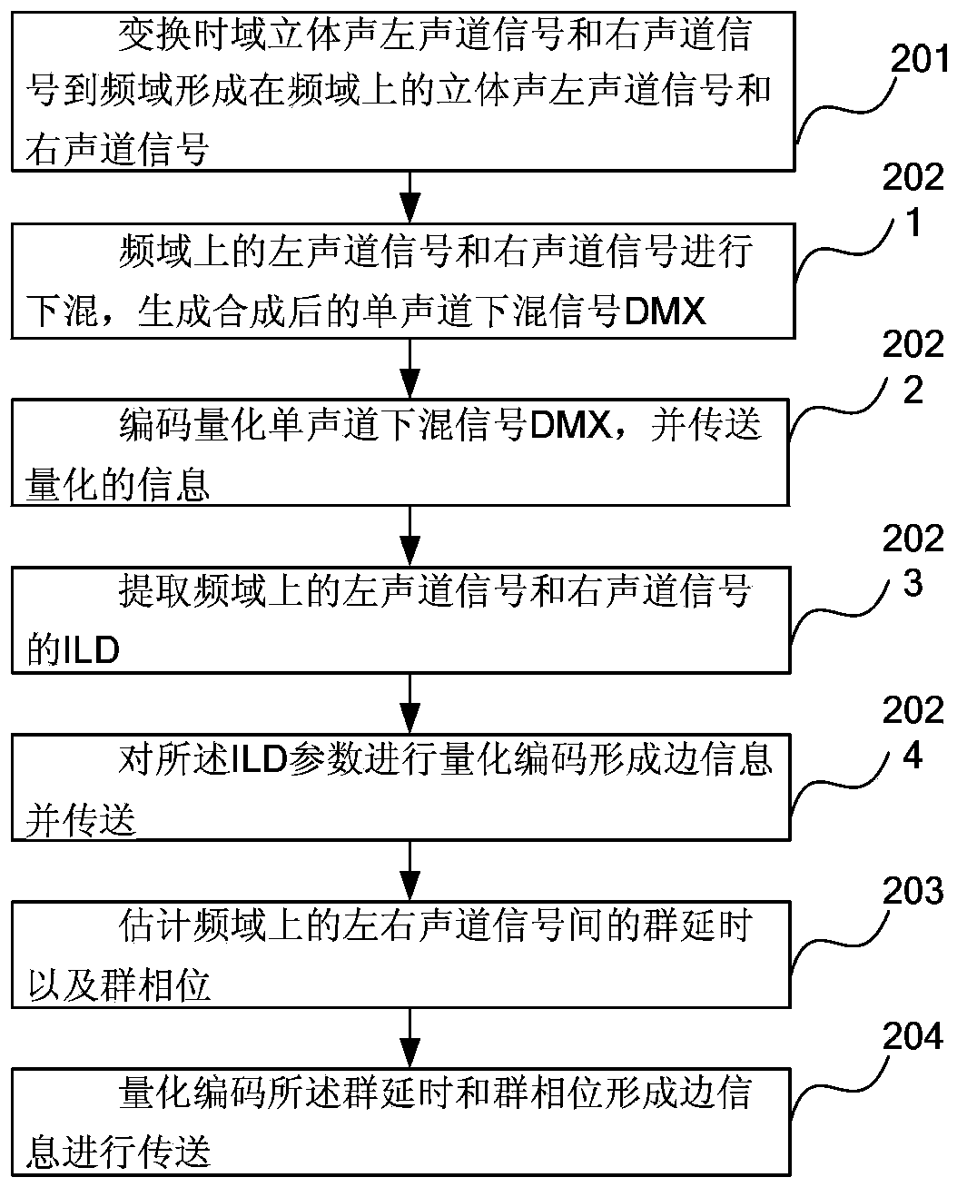
[0042] figure 2 It is a schematic diagram of another stereo encoding method embodiment, including:
[0043] Step 201, transform the time domain stereo left channel signal and the right channel signal to the frequency domain to form the stereo left channel signal X on the frequency domain 1 (k) and right channel signal X 2 (k), where k is the index value of the frequency point of the frequency signal.
[0044] Step 202, performing a downmix operation on the left channel signal and the right channel signal in the frequency domain, encoding and quantizing the downmix signal and transmitting, and encoding stereo space parameters, quantizing to form side information and transmitting, may include the following steps:
[0045] In step 2021, the left channel signal and the right channel signal in the frequency domain are downmixed to generate a synthesized mono channel downmix signal DMX.
[0046] Step 2022, encode the quantized mono-channel downmix signal DMX, and transmit the qu...
Embodiment approach
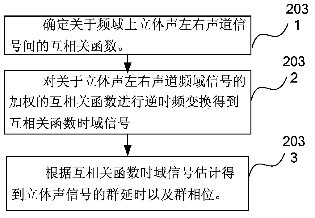
[0077] Step 2033 implementation mode one, such as Figure 4a Shown:
[0078] According to the cross-correlation function time-domain signal or based on the index corresponding to the value with the largest amplitude in the processed cross-correlation function time-domain signal, the group delay is obtained, and the phase angle corresponding to the cross-correlation function corresponding to the group delay is obtained, and the group phase is estimated. , including the following steps:
[0079] Judging the relationship between the index corresponding to the value with the largest amplitude in the cross-correlation function of the time-domain signal and the symmetrical interval related to the transformation length N, in one embodiment, if the index corresponding to the value with the largest amplitude in the cross-correlation function of the time-domain signal is less than or equal to N / 2, then the group delay is equal to the index corresponding to the value with the largest am...
PUM
 Abstract
Description
Claims
Application Information
PatSnap Eureka turns technology decisions into work you can execute. Powered by our Innovation Knowledge Graph, it runs expert workflows across engineering, life sciences, materials and intellectual property. Get your review-ready output in minutes.


