LED (light-emitting diode) constant current driving circuit

A constant current drive, LED indicator technology, applied in the direction of electric lamp circuit layout, electric light source, electrical components, etc., can solve the problem of weakening the brightness of LED lamps, and achieve the effect of simple circuit and low cost

Inactive Publication Date: 2013-10-23
HONG FU JIN PRECISION IND (SHENZHEN) CO LTD +1
View PDF0 Cites 0 Cited by
  • Summary
  • Abstract
  • Description
  • Claims
  • Application Information

AI Technical Summary

Problems solved by technology

For example, when an electronic device is powered by a battery, as the power of the battery decreases, the current will decrease, and the brightness of the LED light will also decrease.

Method used


Image

  • LED (light-emitting diode) constant current driving circuit

Examples


Embodiment Construction

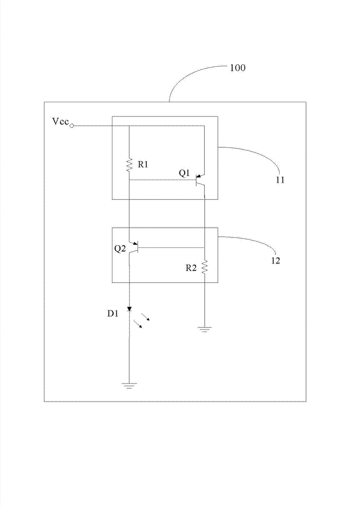
[0009] see figure 1 , is a circuit diagram of the LED constant current drive circuit in an embodiment of the present invention. The LED constant current driving circuit 100 includes a constant current module 11 , a current follower module 12 and an LED indicator. The constant current module 11 is connected to the power supply terminal V cc connected for the power supply terminal V cc The input power supply current is stabilized at a predetermined value, and the current follower module 12 is connected between the constant current module 11 and the LED indicator light D1 for following the current output by the constant current module 11 to further stabilize the power supply current, Thus, a stable current is provided to the LED indicator D1.

[0010] Specifically, such as figure 1 As shown, the constant current module 11 is composed of a current detection resistor R1 and a first triode Q1. The emitter junction of the transistor Q2 is connected in parallel. The current foll...


PUM


Abstract

The invention provides an LED (light-emitting diode) constant current driving circuit, which comprises a constant current module, a current follower module and a load LED indicator light, wherein the constant current module is connected with a power supply input end; current input by the power supply input end is constant at a preset value; and the current follower module is connected between the constant current module and the LED indicator light, so as to further stabilize the current output by the constant current module. By adopting the circuit provided by the invention, the current flowing through the LED indicator light can be constant, and the brightness of the LED indicator light is kept invariant, so that the LED constant current driving circuit is applicable to indicator lights of various electronic devices, the simplicity is realized, and the cost is low.

Description

technical field [0001] The present invention relates to an LED driving circuit, in particular to a constant current driving circuit capable of making the current flowing through the LED constant under the condition of changing input voltage. Background technique [0002] The brightness of the LED light is determined by the magnitude of the current flowing through it. When the input voltage changes, the current flowing through the LED lamp will change, and the brightness of the LED lamp will also change. When the current flowing through the LED lamp increases, the brightness of the LED lamp will become stronger, and vice versa. For example, when an electronic device is powered by a battery, as the power of the battery decreases, the current will decrease, and the brightness of the LED light will also decrease. In actual electronic products, in many places, such as the power-on status indication of the electronic product, the brightness of the LED light is required to remain ...

Claims


Application Information

Patent Timeline
Patent Type & Authority Applications(China)
IPC IPC(8): H05B37/02
CPCH05B33/0812H05B37/02H05B45/395Y02B20/30
Inventor 唐兴华
Owner HONG FU JIN PRECISION IND (SHENZHEN) CO LTD
Why Eureka
Try Eureka