
Hand-held tools and components thereof

A technology of hand-held tools and head components, which is applied in the direction of manufacturing tools, parts of grinding machine tools, metal processing machinery parts, etc.

Inactive Publication Date: 2013-10-23
CAMPBELL HAUSFELDSCOTT FETZER
View PDF5 Cites 3 Cited by
  • Summary
  • Abstract
  • Description
  • Claims
  • Application Information

AI Technical Summary

Problems solved by technology

The housing defines the motor compartment
The head assembly defines a head compartment

Method used


Image

  • Hand-held tools and components thereof
  • Hand-held tools and components thereof
  • Hand-held tools and components thereof

Examples


Embodiment Construction

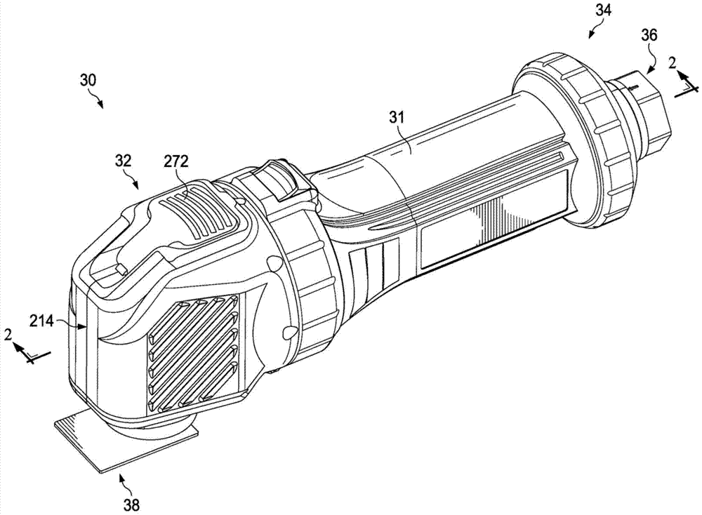
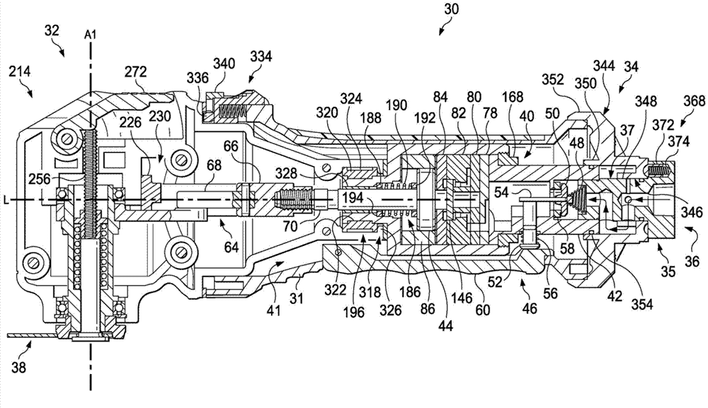
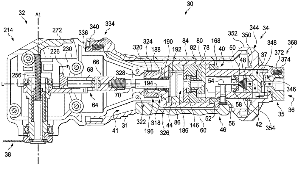
[0055] Hereinafter, with Figure 1-42 Embodiments are described in detail with reference to the drawings and examples, wherein like reference numerals designate like or corresponding elements throughout the drawings. According to one embodiment, as figure 1 and 2 As shown, a hand-held pneumatic oscillating tool 30 (hereinafter “oscillating tool”) may include a housing 31 and may extend between a front end 32 and a rear end 34 . Such as figure 2 As shown, an air inlet 36 may be disposed at the rear end 34 and supported by the housing 31 , and may include a base 35 and a stem 37 . The base 35 of the air inlet 36 may be coupled to an air compressor (not shown) or another source of pressurized air or other fluid. Pressurized air may facilitate selective powering of the oscillating tool 30, which may actuate the auxiliary paddle 38 so that the oscillating tool may be operated as a hand-held knife.

[0056] Such as Figure 2-4 As shown, the oscillating tool 30 may include a l...


PUM


Abstract

In accordance with one embodiment, a hand-held tool comprises a housing, a head assembly, an air inlet, a pneumatic linear motor, a transmission assembly, and at least one resilient member. The housing defines a motor compartment. The head assembly defines a head compartment. The air inlet is supported by the housing. The pneumatic linear motor is disposed at least partially within the motor compartment and comprises a piston. The piston comprises a shaft. The piston is configured for reciprocation between a forward position and a rearward position. The transmission assembly is coupled to the shaft and is disposed at least partially within at least one of the motor compartment and the head compartment.

Description

[0001] Cross References to Related Applications [0002] This application claims serial numbers 61 / 581,731 of "Pneumatic Tools, Components Thereof, and Methods," filed December 30, 2011 and 61 / 646,594 of "Pneumatic Tools, Components Thereof, and Methods," filed May 14, 2012 Serial No. Priority of the US Provisional Patent Application, the entire disclosure of which is hereby expressly incorporated herein by reference. technical field [0003] The present application generally relates to a handheld oscillating tool and components thereof. Background technique [0004] A handheld oscillating tool has a motor and an auxiliary linkage for supporting an auxiliary paddle. Operating the hand-held oscillating tool can oscillate the auxiliary paddle used on the work surface. Contents of the invention [0005] According to one embodiment, a handheld tool includes a housing, a head assembly, an air inlet, a pneumatic linear motor, a transmission assembly, and at least one resilient...

Claims


Application Information

Patent Timeline
IPC IPC(8): B24B7/00
CPCB23Q5/06B24B23/043B25F5/006B24B47/14B25F5/00B24B47/16
Inventor J.K.麦克罗伯茨B.E.帕克斯K.J.维尔什D.R.哈珀K.N.莱J.D.威尔逊
Owner CAMPBELL HAUSFELDSCOTT FETZER
Learn More