Method for controlling a pedal-driven vehicle and control device

A technology of driving device and adjusting device, which is applied to vehicle components, rider driving, transportation and packaging, etc., and can solve problems that have not been considered

Active Publication Date: 2013-10-30
ROBERT BOSCH GMBH
View PDF9 Cites 17 Cited by
  • Summary
  • Abstract
  • Description
  • Claims
  • Application Information

AI Technical Summary

Problems solved by technology

This fact has not been

Method used


Image

  • Method for controlling a pedal-driven vehicle and control device
  • Method for controlling a pedal-driven vehicle and control device
  • Method for controlling a pedal-driven vehicle and control device

Examples


Embodiment Construction

[0044] The invention is schematically illustrated with the aid of the embodiments in the drawings and is described in detail below with reference to the drawings.

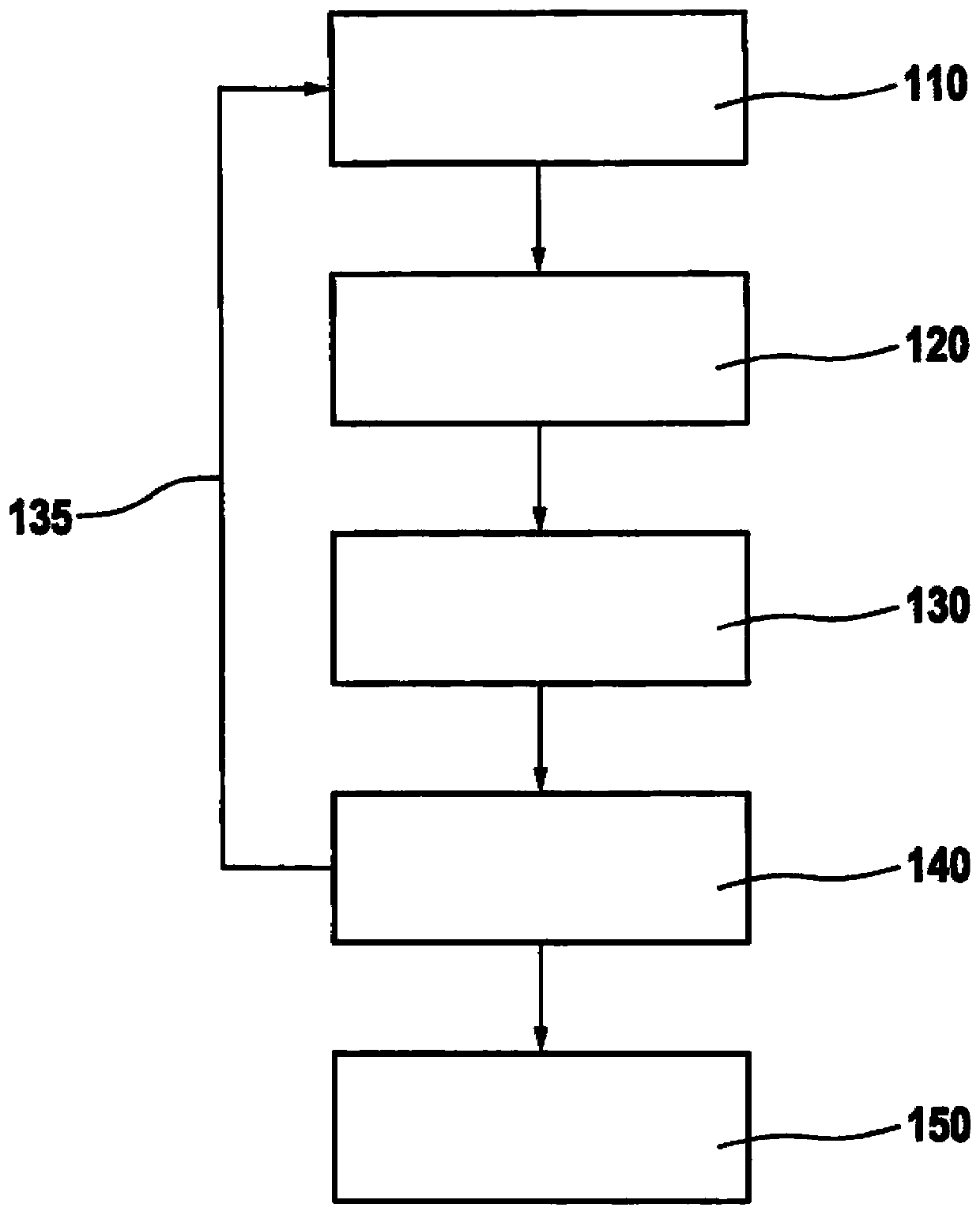
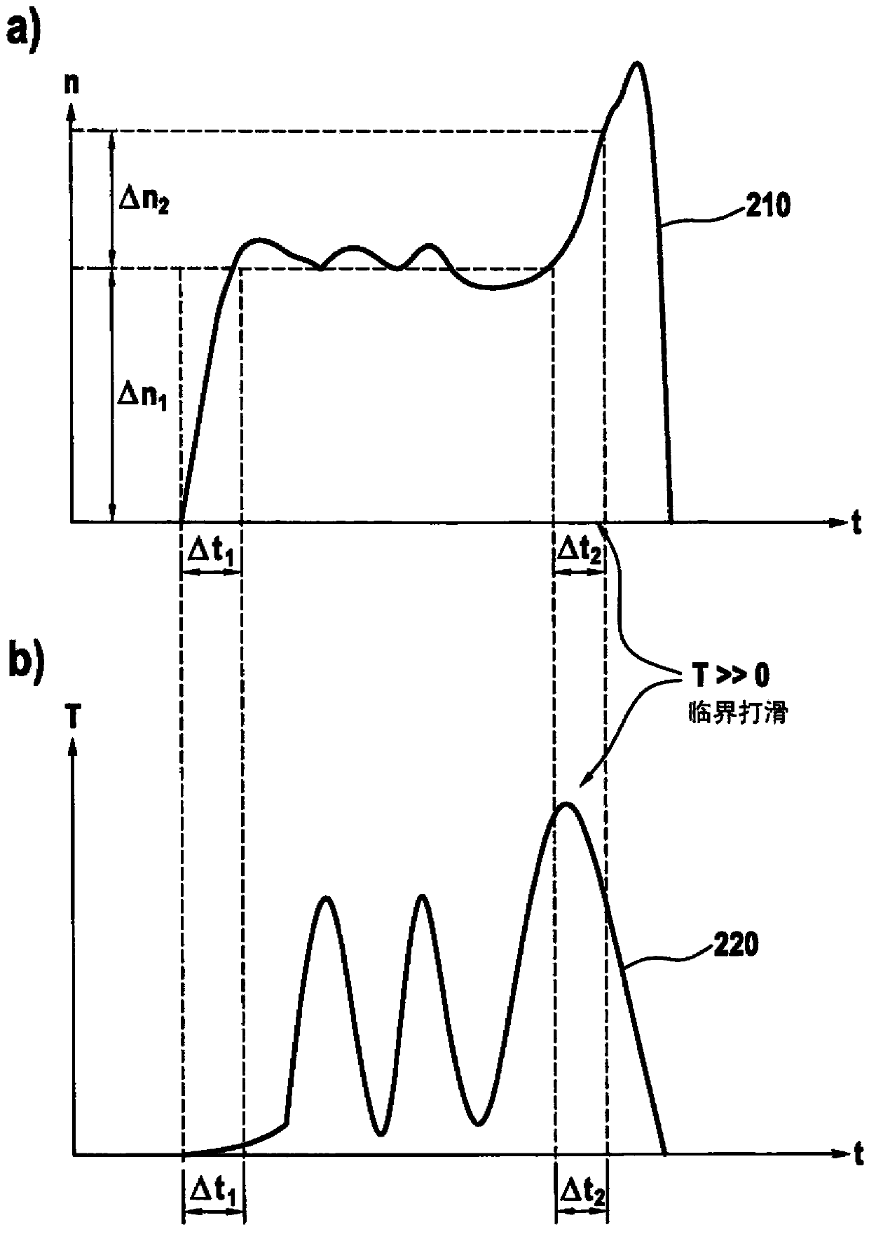
[0045] in figure 1 , Shows the method steps for recognizing an increased slip state according to the first embodiment of the present invention in a vehicle configured as an electric bicycle (also referred to as an electric bicycle or an electric assisted bicycle). In order to detect the current slipping state, in this example, in the first step 110, the pedal speed change Δn over a certain period of time Δt is measured, or in other words the pedal acceleration is measured. As can be directly understood, the pedal acceleration Related to the rotational speed of the driven wheel. Therefore, the pedal acceleration In this embodiment, the sliding parameter according to the present invention is formed. Alternatively, it can be considered that the pedal acceleration is directly detected by a gyroscope (rotational acceler...


PUM


Abstract

The invention provides a pedal-driven vehicle (1) with a drive unit (12). The vehicle includes a pedal-driven apparatus (25) and a motor (10) as an auxillary device. The method involves detecting a slip factor (n, nmot), where the slip factor is detected as an alteration of pedal rotation speed over a turning rate sensor at the driven wheel. A pedal rotational torque is detected (130), and a drive unit is controlled based on the detected slip factor. A sum of the motor torque and the pedal rotational torque is controlled based on the detected slip factor.

Description

Technical field [0001] The present invention relates to a method for adjusting a pedal-driven vehicle which has a drive unit and includes a pedal drive device and a motor as an auxiliary drive device. The invention further relates to regulating devices for such vehicles, as well as to such vehicles having regulating devices. Background technique [0002] In a vehicle with a pedal drive and a motor as an auxiliary drive, especially in a two-wheeled vehicle with an auxiliary drive (so-called electric bicycle (electric bicycle) or Pedelec (electric assist bicycle)), normal driving is understood as The motor torque follows the pedal torque. The motor torque can be either proportional to the pedal torque or approximately constant according to an intermediate value or attenuation assist. Therefore, torque peaks appear at some points in time, at which the driver Apply the maximum force to the pedals. This is completely desirable because it produces a natural driving feel. When the driv...

Claims


Application Information

Patent Timeline
IPC IPC(8): B62M6/45
CPCB62M6/45
Inventor D·席费德克尔W·朔克G·达斯巴赫D·鲍姆格特纳G·维德迈尔
Owner ROBERT BOSCH GMBH
Why Eureka
Try Eureka