Turbo machine

A turbine and impeller technology, applied in the direction of gas turbine devices, lubrication of turbine/propulsion devices, mechanical equipment, etc.

Inactive Publication Date: 2012-01-18
MAN ENERGY SOLUTIONS SE
View PDF5 Cites 1 Cited by
  • Summary
  • Abstract
  • Description
  • Claims
  • Application Information

AI Technical Summary

Problems solved by technology

[0008] The welded connection between the rotor wheel 25 and the shaft 40 configured in this way has repeatedly been damaged in the past durin

Method used


Image

  • Turbo machine
  • Turbo machine
  • Turbo machine

Examples


Embodiment Construction

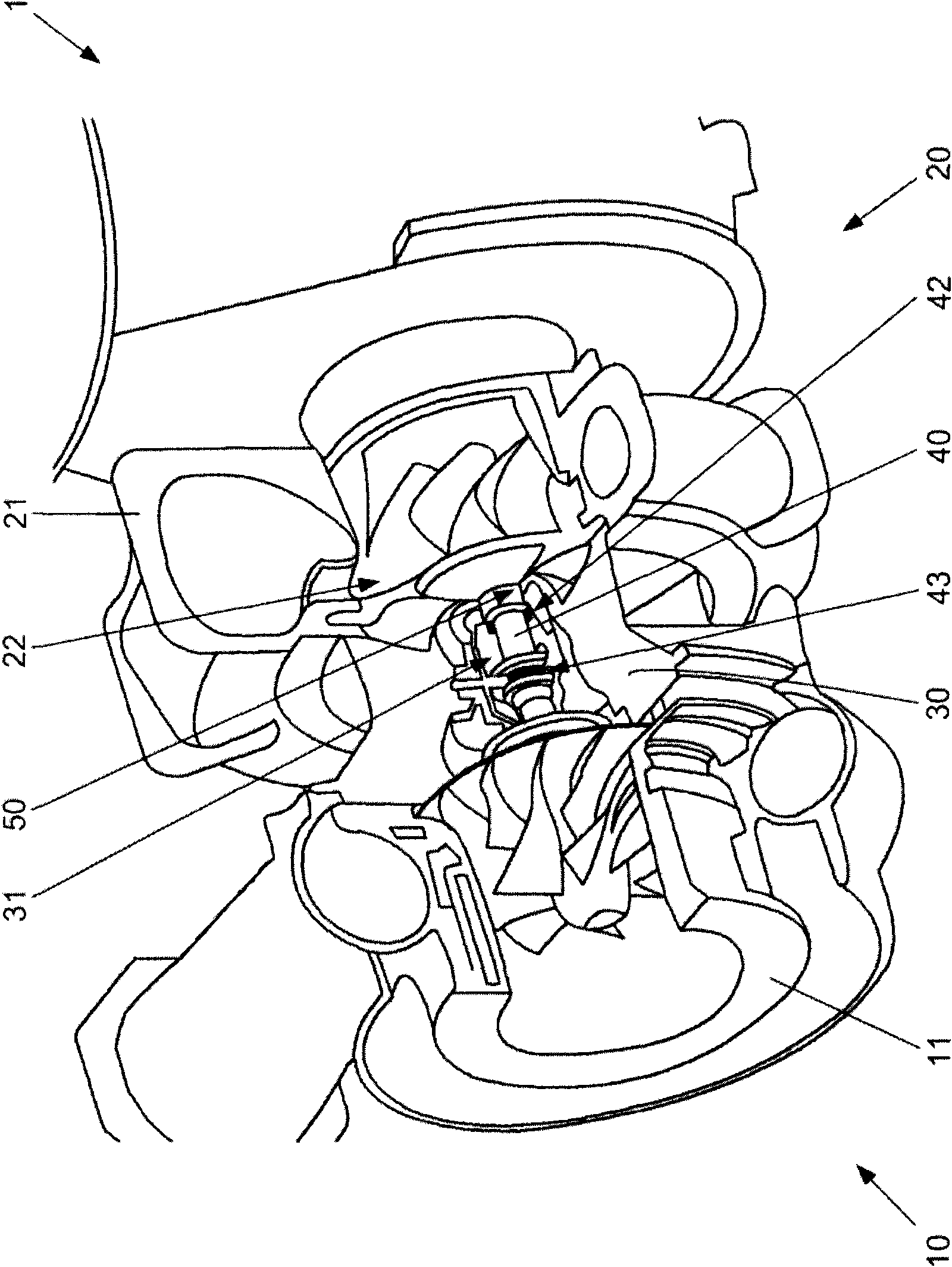
[0079] Refer below figure 1 and 3 A first embodiment of the present invention is described.

[0080] The turbomachine 1 according to the invention is designed in the form of a turbocharger with a turbocompressor 10 and an exhaust gas turbine 20 . The turbomachine 1 has a compressor housing 11 , a turbine housing 21 and a bearing housing 30 connecting the compressor housing 11 to the turbine housing 21 , which is made of ductile iron.

[0081] The turbine 1 also has a shaft 40' made of steel, which is rotatably supported in a bearing housing via a plurality of rotary bearings 42, 43 (here two radial sliding bearings 42 and one axial sliding bearing 43). 30 in the inner chamber 31 (also known as the oil chamber).

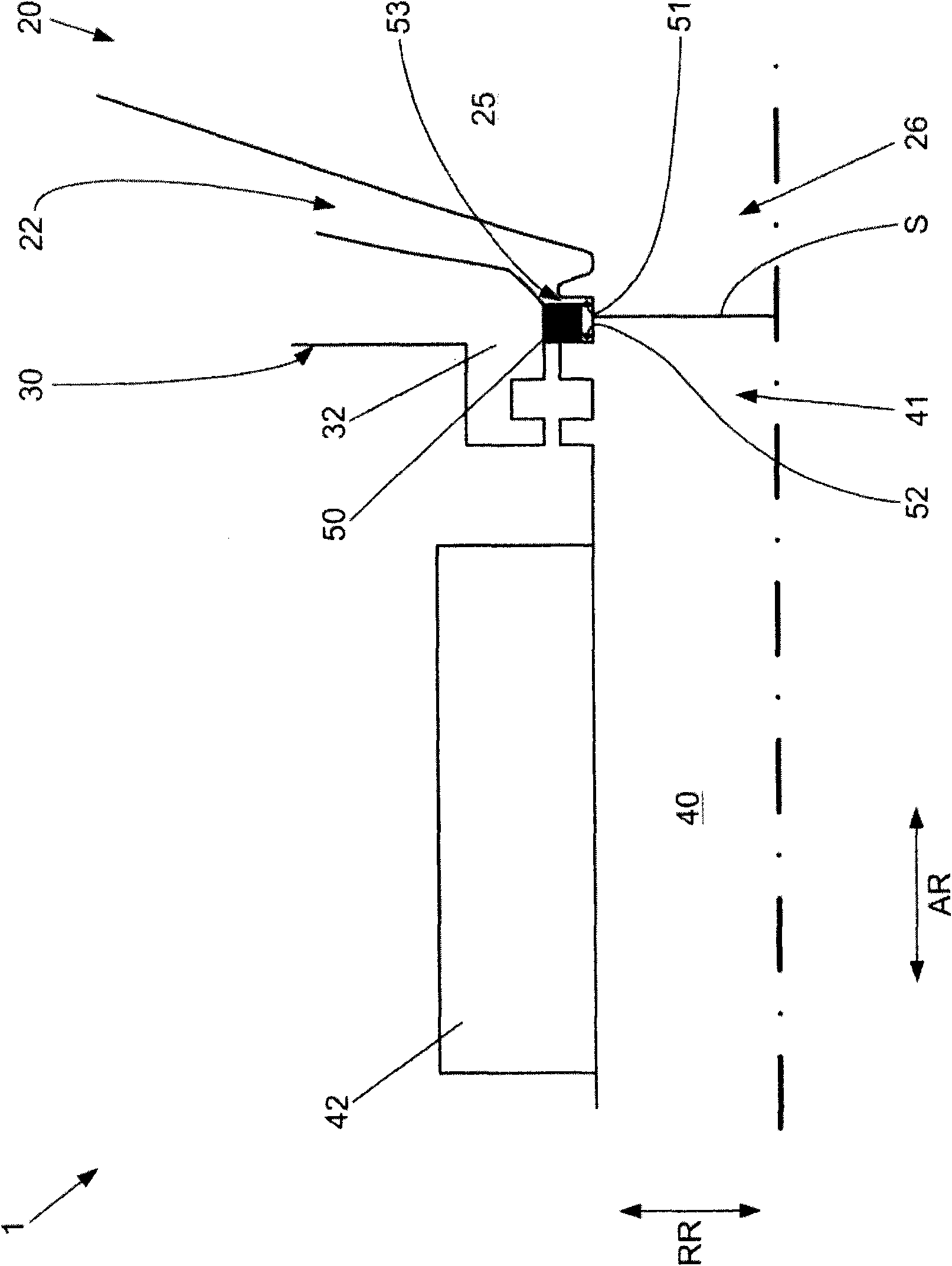
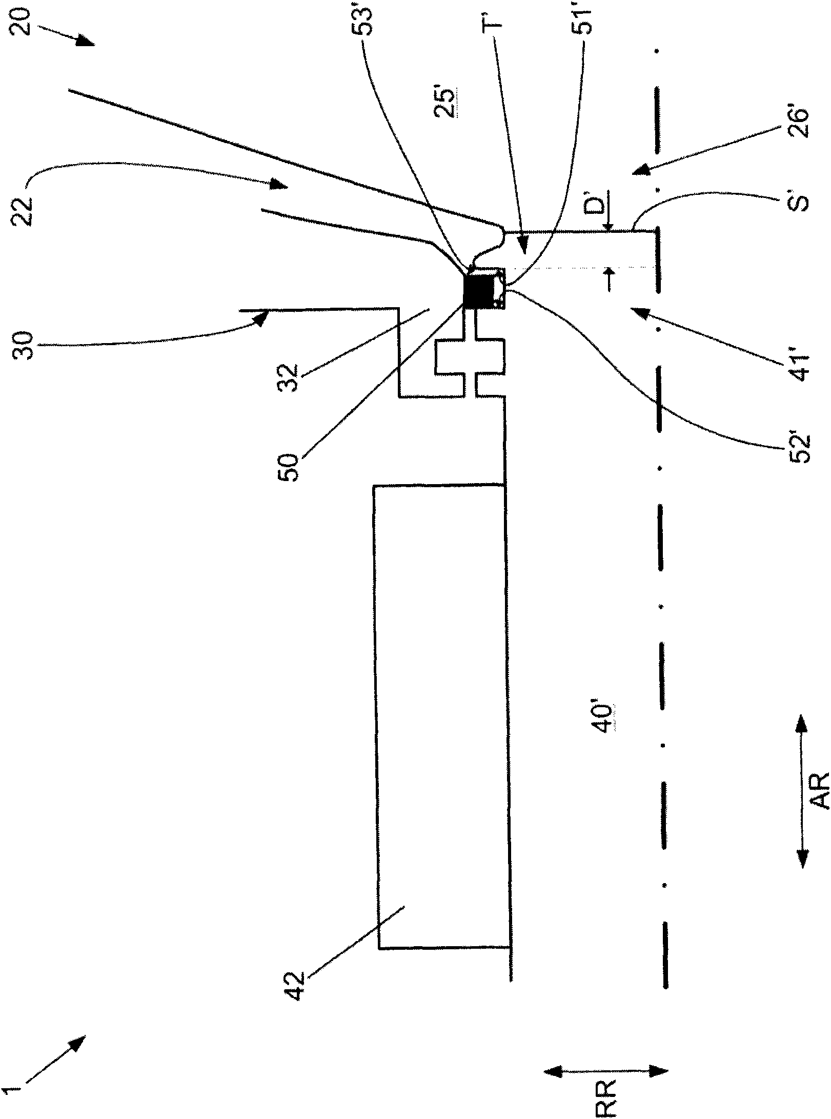
[0082] Such as image 3 As shown, on the axial end 41' of the shaft 40', there is a working impeller 25' of the exhaust gas turbine 20, which is materially connected to the axial end 41' of the shaft 40' by a weld S', and it The rotor chamber 22 of the turbine h...


PUM


Abstract

The invention relates to a turbo machine (1), comprising a bearing housing (30), shafts (40',40'') supported on an inner chamber(31) of the bearing housing (30) rotatably, working impellers(25',25'') connected with longitudinal end parts(41',41'') of the shafts (40',40'') on a material and arranged on the outside of the inner chamber(31) and in a working impeller chamber(22), and a seal member(50) arranged on the circumferences of the shafts (40',40'') to thereby seal the inner chamber(31) relative to the working impeller chamber(22); wherein, the seal member is used for sealing the common effect of two seal surfaces(51',52',51'',52'') rotated oppositely. The invention aims to provide a turbo machine which prevents an undesired welded loose release between the working impellers and the shafts reliably by forming and arranging the seal surface materials of at least one seal surface of the two seal surfaces on isolation layers(T',T'') between the seal member and the working impellers.

Description

technical field [0001] The invention relates to a turbomachine according to the preamble of claim 1 . Background technique [0002] figure 2 combine figure 1 The turbine 1 is shown in the form described above. The turbomachine 1 is designed in the form of a turbocharger and has a turbocompressor 10 and an exhaust gas turbine 20 . The turbomachine 1 has a compressor housing 11 , a turbine housing 21 and a bearing housing 30 connecting the compressor housing 11 to the turbine housing 21 , which is made of ductile iron. [0003] The turbine 1 also has a shaft 40 made of steel, which is rotatably mounted on the bearing housing 30 via a plurality of rotary bearings 42, 43 (here two radial sliding bearings 42 and an axial sliding bearing 43). In the inner chamber 31 (also known as the oil chamber). [0004] Such as figure 2 As shown, the rotor wheel 25 of the exhaust gas turbine 20 is arranged on the longitudinal end 41 of the shaft 40 , which is materially connected to the...

Claims


Application Information

Patent Timeline
IPC IPC(8): F01D25/16F02C7/28F02C7/06
CPCF01D5/026F02C7/06F01D25/183F02C7/28F01D25/162F02C6/12F01D5/063F01D11/08F01D25/24F02B39/00
Inventor K·巴托洛梅A·博恩霍恩P·肖雷尔
Owner MAN ENERGY SOLUTIONS SE
Why Eureka
Try Eureka