Vacuum valve that closes the flow path with a two-piece disc

A vacuum valve and flow path technology, applied in the valve operation/release device, valve details, valve device, etc., can solve the problems of reduced reliability, weakened sealing effect, etc., to achieve reliable maintenance of sealing effect, simple valve structure, compact And the effect of valve structure

Active Publication Date: 2020-03-10
VAT HLDG AG
View PDF17 Cites 1 Cited by
  • Summary
  • Abstract
  • Description
  • Claims
  • Application Information

AI Technical Summary

Problems solved by technology

[0011] A disadvantage of such an embodiment can be, in particular, that in the event of an increased positive pressure in the volume to be sealed off, the first disk has a reduced sealing effect, although the second disk is supported on the oppo

Method used


Image

  • Vacuum valve that closes the flow path with a two-piece disc
  • Vacuum valve that closes the flow path with a two-piece disc
  • Vacuum valve that closes the flow path with a two-piece disc

Examples


Embodiment Construction

[0074] Figure 1a to Figure 4 The same exemplary embodiment of the valve according to the invention is shown in different states in different views and in different degrees of detail.

[0075] Accordingly, these figures are described together, and reference numerals and features already described in previous figures are sometimes not reintroduced here.

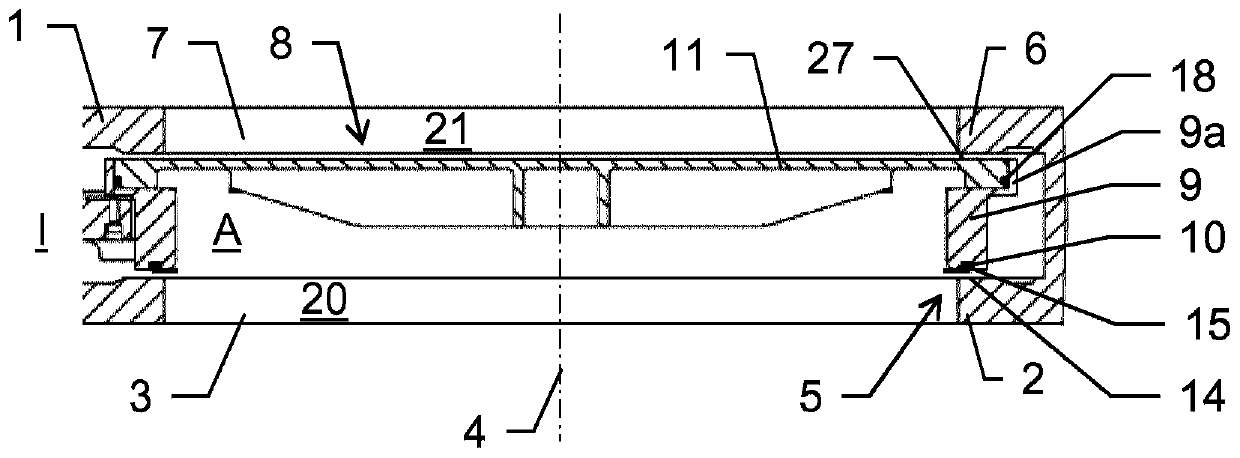
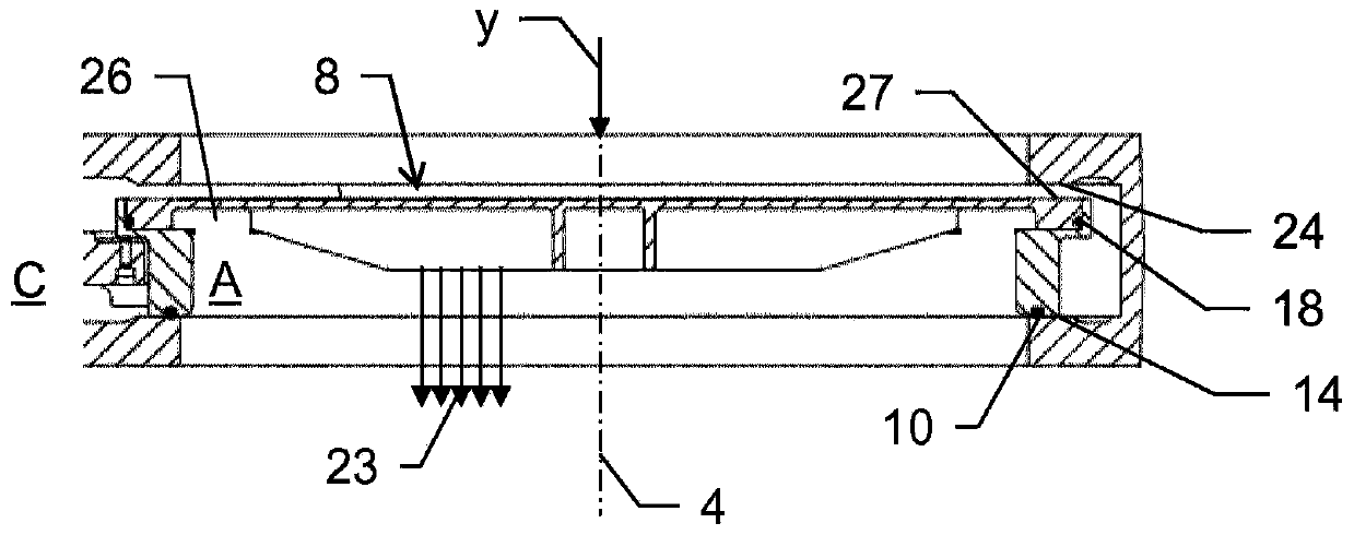
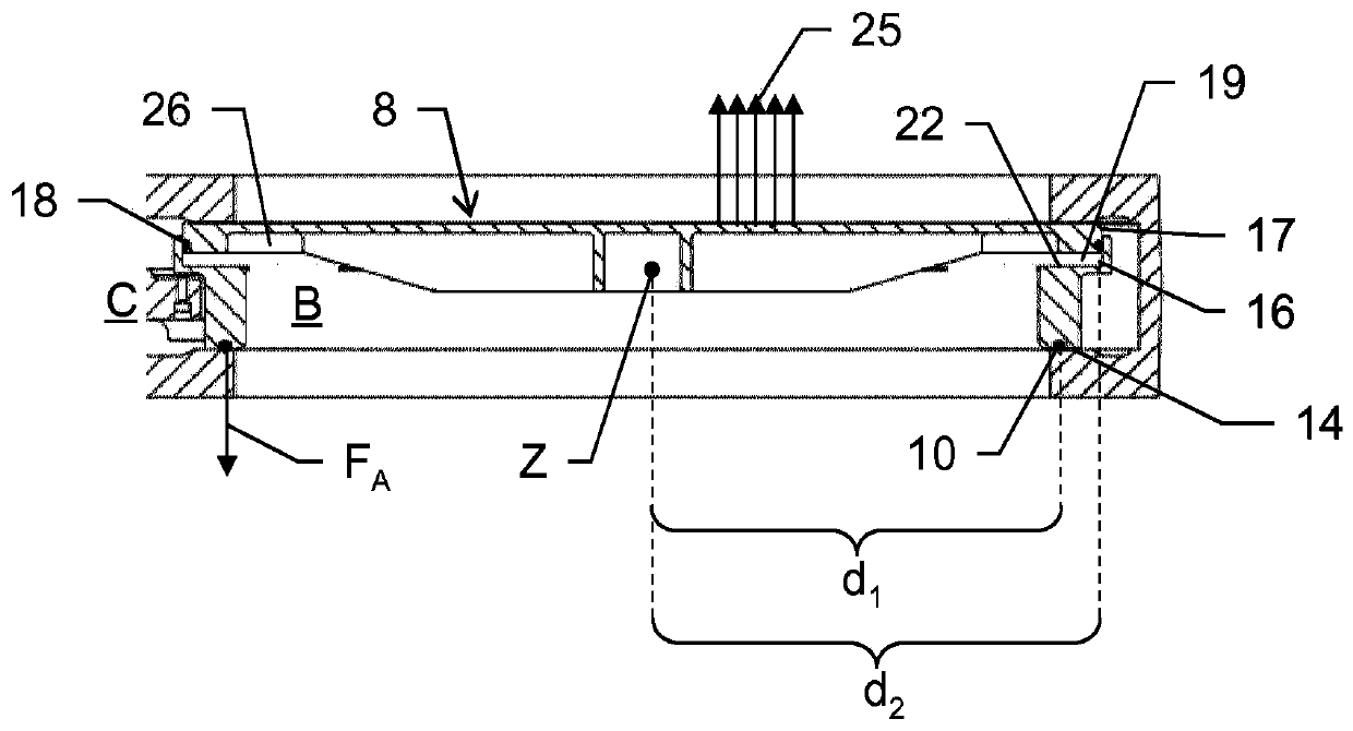
[0076] exist Figure 1a to Figure 4 A possible embodiment of a valve according to the invention in the form of a pendulum valve is shown in . for basic hermetic breaks as in Figure 4 The valve of the flow path F symbolized by an arrow in the middle includes a valve housing 1 having a first opening 3 and an opposing second opening 7 . The two openings 3, 7 have a circular cross-section, but other shapes are also possible. exist Figure 1b , Figure 1c , Figure 2b and Figure 2c In the closed position C of the valve disc 8, the two openings 3, 7 are airtightly separated from each other by the valve disc 8, and the two ...


PUM


Abstract

The invention relates to a vacuum valve for a substantially gas-tight interruption of a flow path, having a valve housing (1) comprising a first opening (3) with a geometric opening axis (4) and a valve seat (5). There is also a valve disc (8) having a first disc portion (9) with an outer boundary (9a) and a second disc portion (11), the second disc portion being parallel to the opening axis (9a) within the outer boundary (9a). 3) in the direction of linear movement and installed in a sealed manner. Controlled mobility of the valve disc (8) is provided by a drive mechanism connected to the first disc portion (9). The first disc (9) has a first contact surface (15) directed axially towards the valve seat (5), the first contact surface being designed to be present in the first contact area with the sealing surface in the closed position (C) (14) Axial sealing contact. The outer boundary (9a) has an inner surface (16) directed radially inward. The second disc portion (11) has a radially outwardly directed outer surface (17) which is designed to exist in sealing contact with the inner surface (16) in the region of the second contact zone. At least for a given radial angle around the center (Z) of the valve disc (8), the first radial distance from the center to the first contact surface is smaller than the second radial distance from the center to the second contact zone.

Description

technical field [0001] The present invention relates to valves for substantially airtight interruption of flow paths. Such valves, in particular in the form of pendulum valves or slide valves, are used in particular in vacuum technology. Background technique [0002] In general, different embodiments of vacuum valves for substantially gas-tight shutoff of a flow, flow or light path through an opening formed in a valve housing are known from the prior art. [0003] Vacuum slide valves are used in particular in the field of IC processing and semiconductor processing, but also, for example, in the field of electron microscopy, which also has to take place in a protected atmosphere which is as free as possible of dirt particles. [0004] For example, in processing plants for semiconductor wafers or liquid crystal substrates, highly sensitive semiconductor elements or liquid crystal elements are thus passed through a plurality of processing chambers, in which the semiconductor e...

Claims


Application Information

Patent Timeline
IPC IPC(8): F16K51/02F16K3/10F16K3/314F16K31/04
CPCF16K3/10F16K3/314F16K31/041F16K51/02F16K3/188
Inventor C·博姆M·特龙卡W·维斯
Owner VAT HLDG AG
Why Eureka
Try Eureka