Damper device

a technology of damper device and axial size, which is applied in the direction of mechanical actuator clutch, mechanical actuation clutch, coupling, etc., can solve the problems of damper device, incompatibility with serialized type of damper device, hysteresis generating mechanism, etc., to reduce gaps between axially adjacent members, reduce the gap between members, and the axial size of the damper device is compact.

Pending Publication Date: 2022-06-16
EXEDY CORP
View PDF0 Cites 2 Cited by
  • Summary
  • Abstract
  • Description
  • Claims
  • Application Information

AI Technical Summary

Benefits of technology

[0010]In the present damper device, when a torque is inputted to the first rotor, for instance, the torque is transmitted to the second rotor through the plurality of elastic members. When the torque inputted to the first rotor fluctuates, the torque fluctuations are inhibited by the actuation of the plurality of elastic members and by the hysteresis generating mechanism, whereby vibrations are attenuated. Especially, at least two elastic members are actuated in series by the intermediate member. Hence, increase in torsion angle (widening of angle) is achieved, whereby the vibrations attributed to the torque fluctuations can be attenuated as much as possible.
[0019]Here, for realizing compactness in axial size of the damper device, it is required to reduce gaps between axially adjacent members as much as possible. On the other hand, for inhibiting unintended generation of hysteresis torque, it is required to avoid frictional contacts between members in parts other than the hysteresis generating mechanism. For thus reducing the gaps between members as much as possible and simultaneously avoiding the frictional contacts between those members, it is required to manage both machining of members and assembling of members with high accuracy.

Problems solved by technology

However, the hysteresis generating mechanism, used for the type of damper device in which the plural springs are actuated in parallel, is incompatible to the serialized type of damper device.

Method used


Image

  • Damper device
  • Damper device
  • Damper device

Examples


Embodiment Construction

[Entire Configuration]

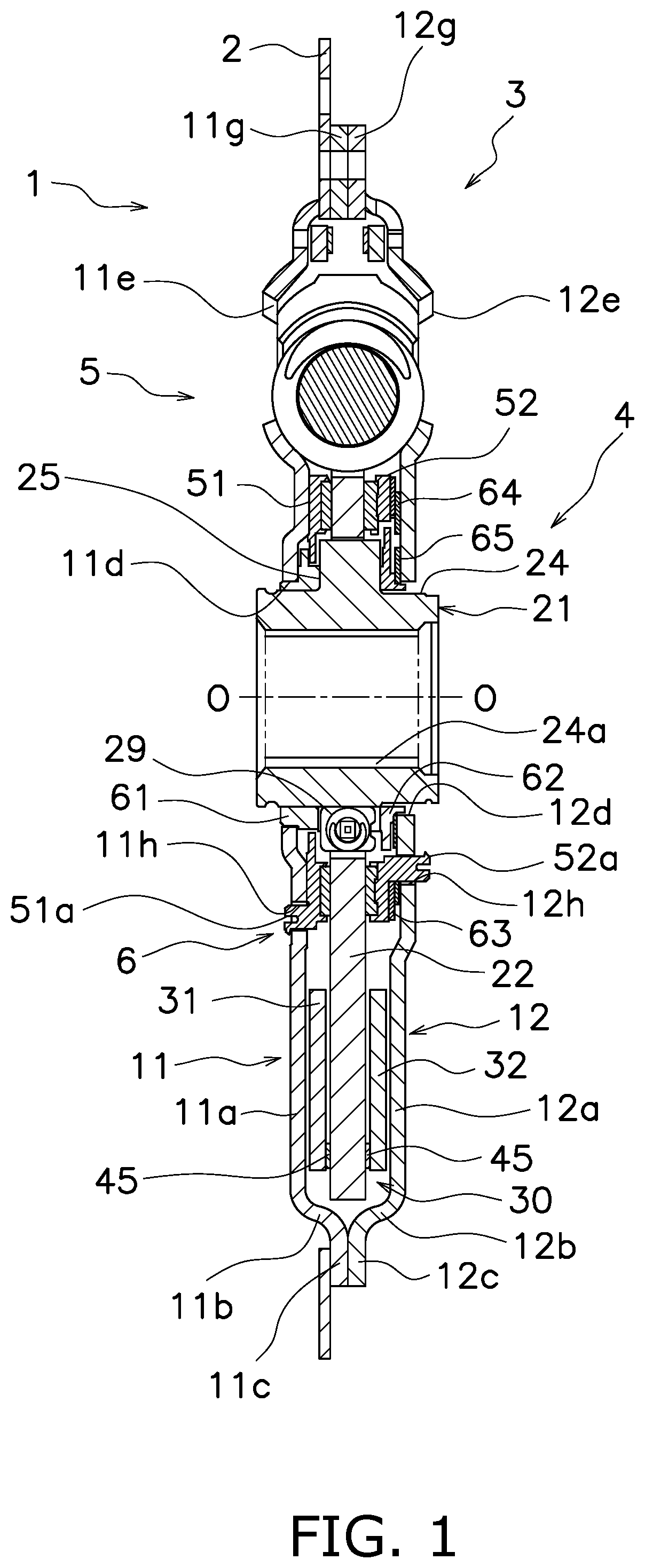
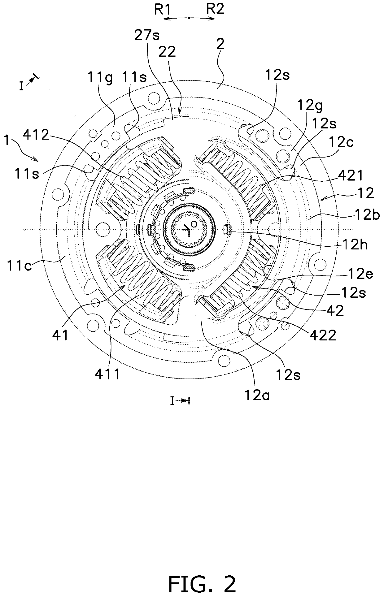
[0032]FIG. 1 is a cross-sectional view of a damper device 1 according to a preferred embodiment of the present invention and is taken along line I-I in FIG. 2. On the other hand, FIG. 2 is a front view of the damper device 1, from part of which some constituent members are detached. In FIG. 1, a drive source is disposed on the left side of the damper device 1, whereas a transmission and so forth are disposed on the right side of the damper device 1.

[0033]It should be noted that in the following explanation, the term “axial direction” refers to an extending direction of a rotational axis O of the damper device 1. On the other hand, the term “circumferential direction” refers to a circumferential direction of an imaginary circle about the rotational axis O, whereas the term “radial direction” refers to a radial direction of the imaginary circle about the rotational axis O. It should be noted that the circumferential direction is not required to be perfectly match...


PUM


Abstract

A damper device includes a first rotor, a second rotor rotatable relative to the first rotor, a plurality of elastic members circumferentially aligned, an intermediate member, and a hysteresis generating mechanism. The intermediate member is disposed axially between the first rotor and the second rotor. The hysteresis generating mechanism is disposed axially between the first rotor and the second rotor to generate a hysteresis torque in relative rotation between the first rotor and the second rotor. The intermediate member includes an annular portion and a support portion. The annular portion is provided radially outside the plurality of elastic members. The support portion protrudes radially inward from the annular portion. The support portion is disposed between at least circumferentially adjacent two of the plurality of elastic members. The support portion actuates the at least circumferentially adjacent two of the plurality of elastic members in series.

Description

CROSS-REFERENCE TO RELATED APPLICATIONS[0001]This application claims priority to Japanese Patent Application No. 2020-208343 filed Dec. 16, 2020. The entire contents of that application are incorporated by reference herein in their entirety.TECHNICAL FIELD[0002]The present invention relates to a damper device.BACKGROUND ART[0003]A power transmission train for a vehicle is provided with a damper device for attenuating vibrations attributed to fluctuations in torque from a drive source. In general, the damper device is provided with an input rotor, an output rotor, a plurality of springs, and a hysteresis generating mechanism. The input rotor and the output rotor are rotatable relative to each other in a predetermined angular range. The springs elastically couple both the rotors in a rotational direction. The hysteresis generating mechanism generates a hysteresis torque in relative rotation between the input rotor and the output rotor. The hysteresis torque attenuates vibrations attri...

Claims


Application Information

Patent Timeline
Patent Type & Authority Applications(United States)
IPC IPC(8): F16D3/12F16F15/123
CPCF16D3/12F16F15/12353F16F2236/08F16F2232/02F16D2300/22F16F15/134F16F15/1343F16F15/139F16F15/1238F16F15/129F16D13/644
Inventor TOMITA, ATSUSHIMIYAUCHI, KOTAROSENOUE, TAKESHI
Owner EXEDY CORP
Why Eureka
Try Eureka