Supercharge Your Innovation With Domain-Expert AI Agents!

Shaft sealing system for steam turbines

A shaft seal and turbine technology, applied in the field of independent shaft seal systems, can solve problems such as damage to seals

Active Publication Date: 2013-10-30
GENERAL ELECTRIC TECH GMBH
View PDF1 Cites 0 Cited by
  • Summary
  • Abstract
  • Description
  • Claims
  • Application Information

AI Technical Summary

Problems solved by technology

However, in seal system designs utilizing carbon seals with much smaller clearances, particulate matter can become trapped in the interstitial space, causing seal damage

Method used


Image

  • Shaft sealing system for steam turbines
  • Shaft sealing system for steam turbines
  • Shaft sealing system for steam turbines

Examples


Embodiment Construction

[0056] At least one embodiment of the invention is described hereinafter with reference to its application in connection with steam turbine operation. While embodiments of the invention are described with respect to steam turbines, it should be understood that the present teachings are equally applicable to other turbomachinery, including but not limited to compressors. Furthermore, at least one embodiment of the invention is described hereinafter with reference to nominal dimensions and including a set of nominal dimensions. However, it should be apparent to those skilled in the art that the invention is equally applicable to any suitable turbine and / or compressor. Furthermore, it should be apparent to those skilled in the art that the present invention is equally applicable to various orders of magnitude and / or nominal dimensions.

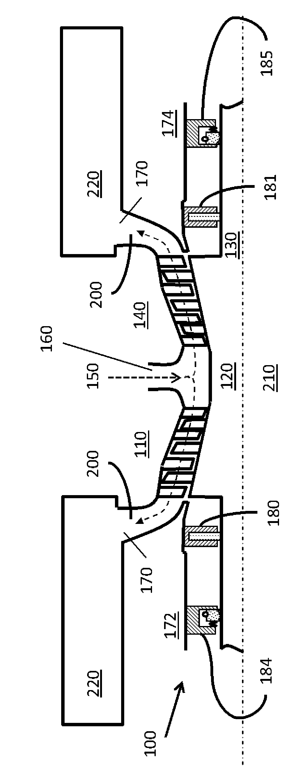
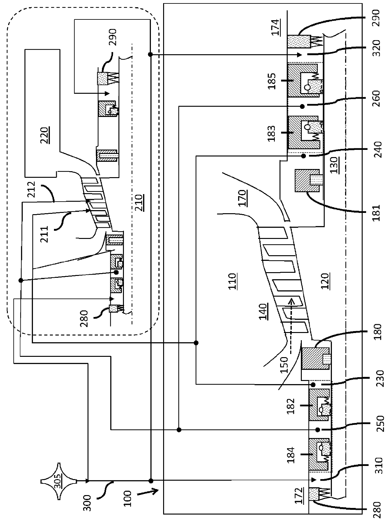
[0057] As noted above, aspects of the present invention provide a shaft sealing system 100, various aspects of which are Figure 1 to Figure 5...


PUM


Abstract

A shaft sealing system and method are disclosed for a high or intermediate pressure turbine section having a rotating member (120) including a shaft (130) and a stationary member (140) surrounding the rotating member (120) and defining a steam flow path (150). The shaft sealing system comprises at least one seal disposed about each of a first end (172) and a second end (174) of the shaft (130); and a connection line (200) for conducting steam from a first turbine section (110) to a downstream portion (210) of the turbine. The downstream portion (210) of the turbine is one of a low pressure section and a condenser (220), and has a lower pressure than both of the first turbine section (110) and ambient pressure conditions.

Description

[0001] Cross References to Related Applications [0002] This patent application is related to commonly assigned US patent application (General Electric Company Docket No. 251445-1) filed concurrently with this application. technical field [0003] The present invention relates generally to steam turbines and, more particularly, to self-contained shaft sealing systems for steam turbines. Background technique [0004] The pressure boundary of the steam turbine casing is penetrated by the rotating turbine shaft in order to transfer the power generated by the turbine to the outside of the steam environment. Therefore, the shaft must be sealed at the point where it penetrates the housing in order to prevent steam from escaping, which could be dangerous to persons in the area. The shaft seal must also prevent air from entering the housing, which can have a detrimental effect on turbine performance. [0005] A variety of shaft sealing systems have been employed including, for e...

Claims


Application Information

Patent Timeline
Patent Type & Authority Applications(China)
IPC IPC(8): F03D11/00F16J15/54
CPCF01D11/003F01D11/04F05D2220/31F05D2260/6022F05D2240/63F16J15/54
Inventor 郑小清D.R.科菲陆国强J.R.鲍威尔斯S.P.斯卡拉塔C.D.萨特尔斯
Owner GENERAL ELECTRIC TECH GMBH
Features
  • R&D
  • Intellectual Property
  • Life Sciences
  • Materials
  • Tech Scout
  • Unparalleled Data Quality
  • Higher Quality Content
  • 60% Fewer Hallucinations
Learn More