Fixing structure

A technology for fixing structures and fixing parts, which is applied in the direction of circuit layout, circuits, connections, etc. on the supporting structure, and can solve problems such as poor appearance of the shell 2 and dents in the shell 2

Inactive Publication Date: 2013-10-30
HONG FU JIN PRECISION IND (SHENZHEN) CO LTD +1
View PDF0 Cites 0 Cited by
  • Summary
  • Abstract
  • Description
  • Claims
  • Application Information

AI Technical Summary

Problems solved by technology

However, due to the existence of the cover 12, when the screw 3 is locked to the stud, the pressure when the screw 3 is locked acts on the cover 12, and when the screw 3 is locked tightly, the cover will 12 will generate a pulling force on the stud 20, since the stud 20 is fixed to the casing 2, the casing 2 will be dented, causing the casing 2 to have a bad appearance

Method used


Image

  • Fixing structure
  • Fixing structure
  • Fixing structure

Examples


Embodiment Construction

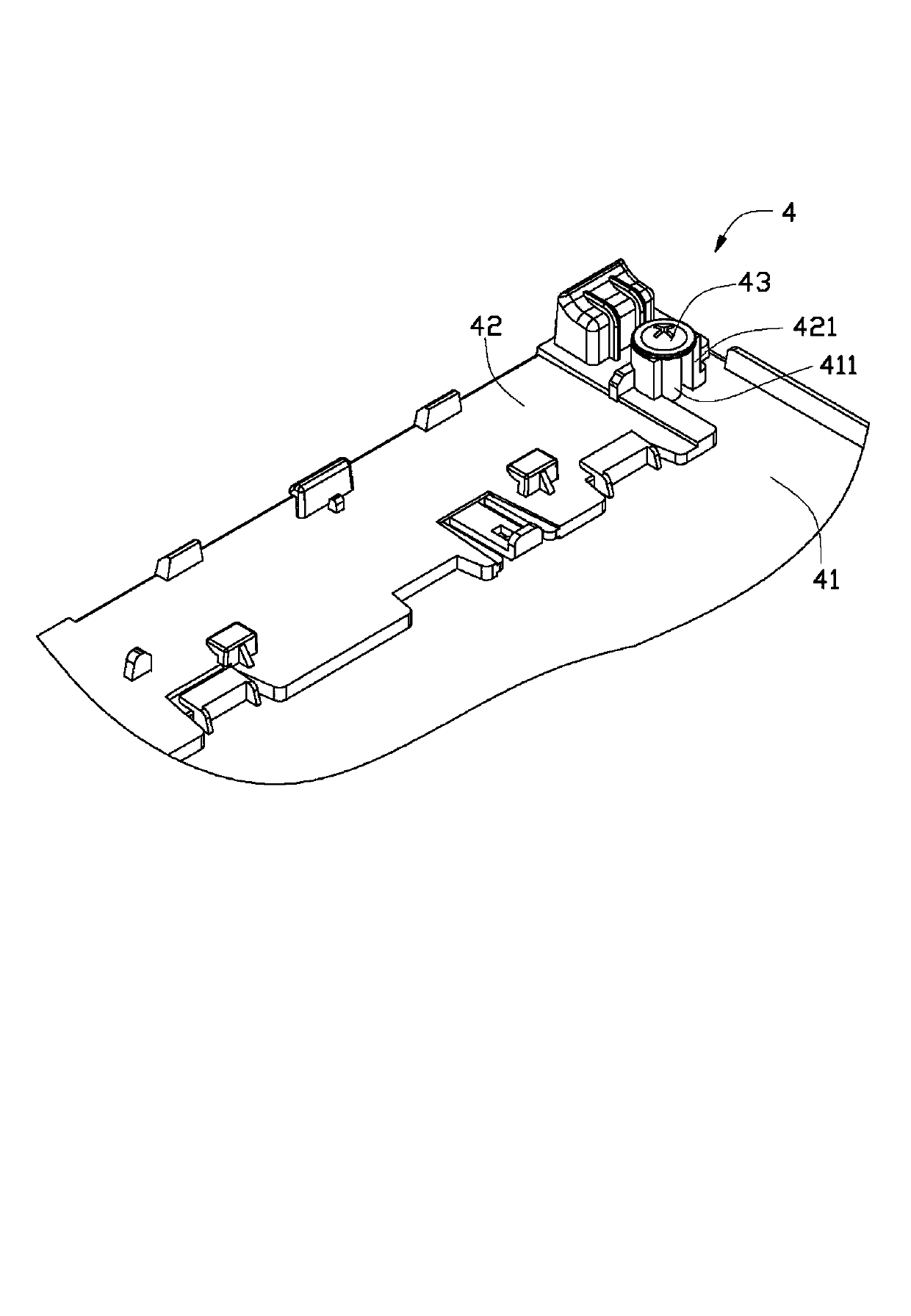
[0012] Such as Figure 3-4 As shown, a fixing structure 4 includes a housing 41, a fixed part 42, and at least one locking part 43. The housing 41 is fixed with at least one fixing post 411, and the fixed part 42 includes at least one support 421, The supporting member 421 is slightly higher than the fixing post 411. The locking member 3 includes a stop portion 31 and a locking portion 32. The locking portion 32 is inserted into the fixing column 411. The supporting member 421 is a flat plate. A flat plate is bent around the fixing post 411, the locking portion 32 is inserted into the fixing post 411, and cooperates with the fixing post 411 to prevent the locking portion from falling off, and the stop portion 32 abuts the support 421 , So that the fixed member 42 is fixed to the housing 41.

[0013] In this embodiment, the housing 41 is a transparent mirror housing, the fixed part 42 is a decorative part, and the locking part 43 and the fixing post 411 are screws and studs, resp...


PUM


Abstract

A fastening structure assembly includes a housing, a to-be-fixed element, and at least one fastening element. The housing defines at least one fastening post. The to-be-fixed element includes at least one supporter each of which is bent to surround one of the at least one fastening post. Each of the at least one fastening element includes a stopper and a fastening pole extending from the stopper. Each of the fastening pole engages with one of the fastening posts to make the corresponding stopper resist an edge of the supporter surrounding the fastening post to fasten the to-be-fixed element to the housing.

Description

Technical field [0001] The present invention relates to a fixing structure, in particular to a fixing structure for fixing a fixed member to a housing through a locking component. Background technique [0002] Such as Figure 1-2 As shown, in the prior art, in a fixing structure 100 for fixing a decorative element 1 to a mirror housing 2, a stud 20 is provided on the mirror housing 2, and a support 10 is provided on the decorative element 1. The support 10 includes a support 11 and a cover 12 fixed to the support 11. A hole 13 is defined on the cover 12, and a screw 3 passes through the hole 13 and cooperates with a stud 20 to make the decoration 1 Fixed on the housing 2. However, due to the presence of the cover 12, when the screw 3 is locked to the stud, the pressure when the screw 3 is locked acts on the cover 12. When the screw 3 is locked tightly, the cover 12 will generate a pulling force on the stud 20. Since the stud 20 is fixed to the housing 2, the housing 2 will be de...

Claims


Application Information

Patent Timeline
Patent Type & Authority Applications(China)
IPC IPC(8): H05K7/12
CPCH05K7/12
Inventor 杨锦松刘威唐学东
Owner HONG FU JIN PRECISION IND (SHENZHEN) CO LTD
Why Eureka
Try Eureka