

Capacitor chip and method for manufacturing same
A technology of capacitors and chips, which is applied in the direction of capacitors, capacitor electrodes, electrolytic capacitors, etc., can solve the problems of the total thickness limitation of stacked capacitor elements, the appearance of pinholes of capacitor elements and poor appearance of bonding wires, etc., and achieve the effect of high electrostatic capacitance
- Summary
- Abstract
- Description
- Claims
- Application Information
AI Technical Summary
Problems solved by technology
Method used
Image

Examples
Embodiment 1
[0061] Aluminum chemical conversion foil (thickness 100um) was cut into 3 mm in the short axis direction x 10 mm in the long axis direction, and a polyimide solution with a width of 1 mm was coated on both sides in a surrounding shape and dried so that the long axis direction It is divided into 4mm sections and 5mm sections, thereby making a masking layer. A voltage of 4 V was applied to a 3 mm x 4 mm portion of the chemical conversion foil in a 10% by mass ammonium adipate aqueous solution, and chemical conversion was performed on the cut portion to form a dielectric oxide film. Next, a 3 mm x 4 mm portion of the aluminum foil was immersed in an isopropyl alcohol (IPA) solution containing 25% by mass of 3,4-ethylenedioxythiophene for 10 seconds, and dried at room temperature for 10 minutes. , and immersed for 10 seconds in a 1 mol / L ammonium persulfate aqueous solution adjusted to 0.05% by mass of 2-anthraquinone sodium sulfonate. Next, this aluminum foil was left to stand a...
Embodiment 2
[0069] The capacitor element with a thickness of 0.25 mm produced in Example 1 was stacked on the upper surface of a metal lead frame with a thickness of 0.1 mm, and two sheets were laminated on the lower surface to produce a capacitor element with a thickness of 1.35 mm including the lead frame. Multilayer capacitor components.
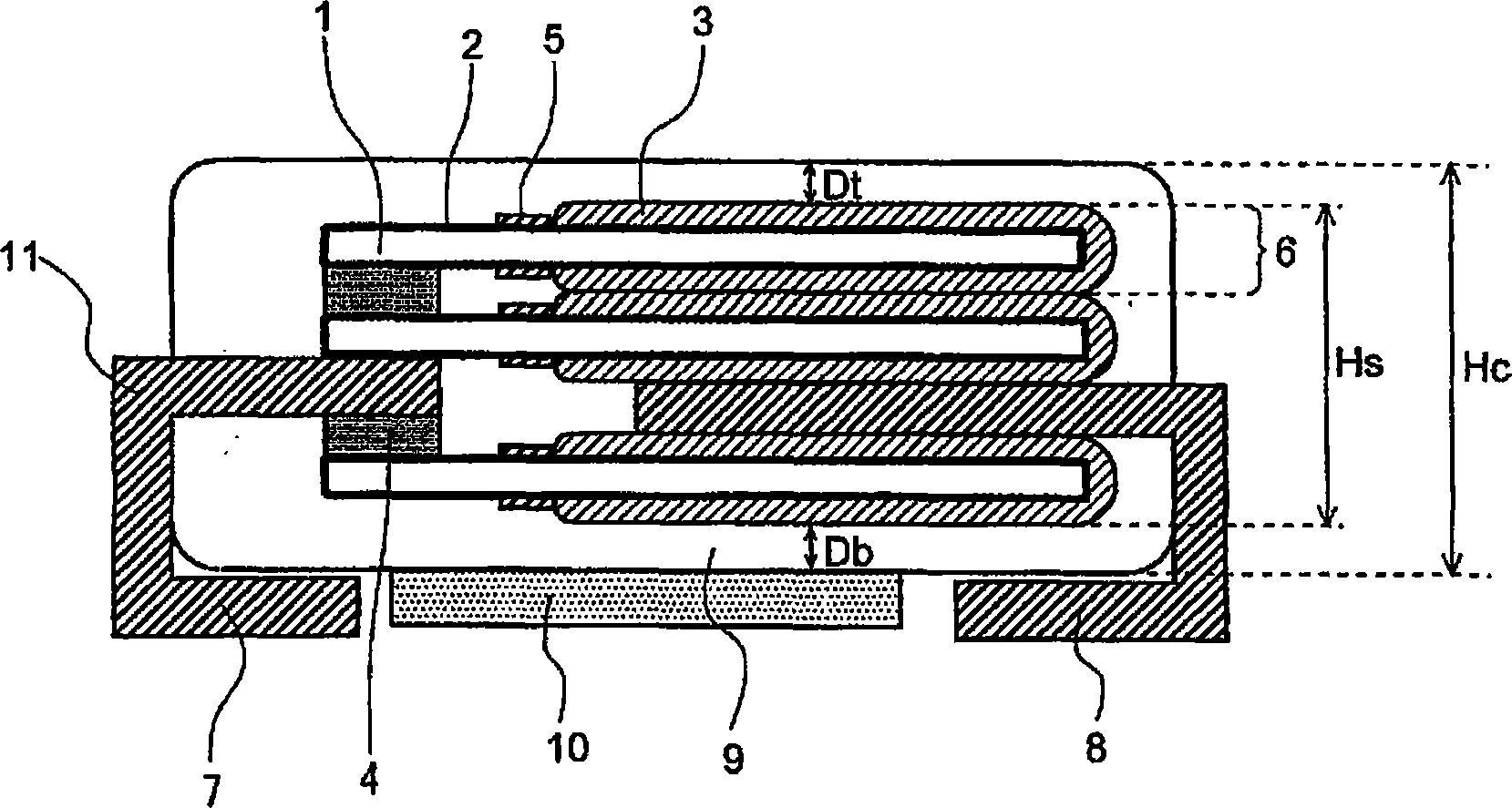
[0070] The same method as in Example 1 was used except that the distance from the upper surface of the laminate to the upper surface of the encapsulating resin was 0.15 mm, and the distance from the lower surface of the laminate to the lower surface of the encapsulating resin excluding the adhesive pad was 0.2 mm. In the same way, 100 capacitor chips with a height of 1.7mm except the bonding pads were produced. In addition, by the same method as in Example 1, an appearance inspection and a measurement of capacitor characteristics were implemented. The results are shown in Table 1 and Table 2.
Embodiment 3
[0072] The capacitor element with a thickness of 0.25 mm produced in Example 1 was stacked on the upper surface of a metal lead frame with a thickness of 0.1 mm, and two sheets were laminated on the lower surface to produce a capacitor element with a thickness of 1.1 mm including the lead frame. Multilayer capacitor components.
[0073] The same method as in Example 1 was used except that the distance from the upper surface of the laminate to the upper surface of the encapsulating resin was 0.3 mm, and the distance from the lower surface of the laminate to the lower surface of the encapsulating resin excluding the adhesive pad was 0.3 mm. In the same way, 100 capacitor chips with a height of 1.7mm except the bonding pads were produced. In addition, by the same method as in Example 1, an appearance inspection and a measurement of capacitor characteristics were implemented. The results are shown in Table 1 and Table 2.
PUM
 Abstract
Description
Claims
Application Information