Manufacturing method of laminated body

A manufacturing method and laminated body technology, applied in semiconductor/solid-state device manufacturing, chemical instruments and methods, lamination, etc., can solve problems such as light-emitting layer, electrode degradation, and poor light emission of components, and achieve the effect of suppressing damage

Active Publication Date: 2020-11-10
SUMITOMO CHEM CO LTD
View PDF6 Cites 0 Cited by
  • Summary
  • Abstract
  • Description
  • Claims
  • Application Information

AI Technical Summary

Problems solved by technology

[0004] However, in organic EL elements, if the light-emitting layer and electrodes come into contact with moisture or oxygen, the light-emitting layer and electrodes will deteriorate, and poor light emission may occur in the element.

Method used


Image

  • Manufacturing method of laminated body
  • Manufacturing method of laminated body
  • Manufacturing method of laminated body

Examples


no. 1 Embodiment approach

[0055] As follows, while referring to Figure 1~4 The manufacturing method of the laminated body which concerns on 1st Embodiment of this invention is demonstrated. In addition, in all the following drawings, in order to make a drawing easy to see, the dimension, ratio, etc. of each component are made to differ suitably.

[0056] [Laminate]

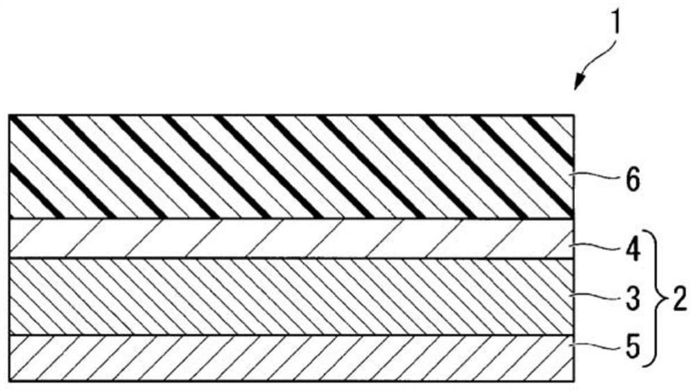
[0057] figure 1 It is a schematic diagram which shows an example of the laminated body manufactured in the manufacturing method of the laminated body of this embodiment. The laminated body 1 has a laminated film 2 and an adhesive layer 6 formed on one surface of the laminated film 2 .

[0058] (laminated film)

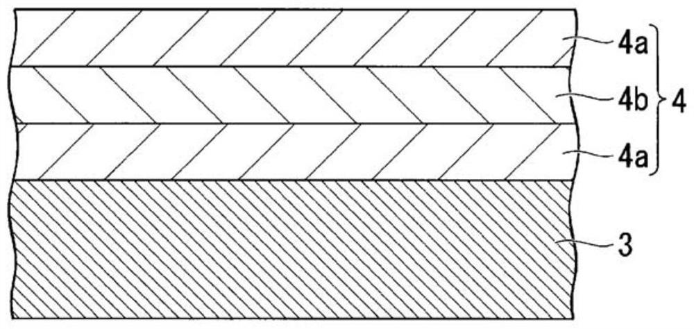
[0059] In the laminated body 1 of the present embodiment, the laminated film 2 has a base material 3, a film layer 4 formed between the base material 3 and an adhesive layer 6, and a film layer provided on the base material 3 and provided with the film layer 4. Curl suppressing layer 5 on the opposite side.

[0060] That is,...

no. 2 Embodiment approach

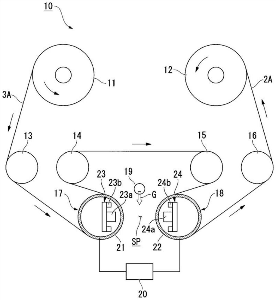
[0196] Figure 5 It is explanatory drawing of the manufacturing method of the laminated body of 2nd Embodiment of this invention. The manufacturing method of the laminated body of this embodiment is partly common to the manufacturing method of the laminated body of 1st Embodiment, and the process of forming an adhesive layer differs. Therefore, in the present embodiment, the same reference numerals are attached to the same components as those in the first embodiment, and detailed description thereof will be omitted.

[0197] (Process of forming an adhesive layer)

[0198] Figure 5 It is an explanatory drawing showing the process of forming an adhesive layer in this embodiment, and it is a schematic diagram of the manufacturing apparatus 200 which implements the process of forming an adhesive layer.

[0199] The manufacturing apparatus 200 shown in the figure is equipped with the 1st unwinding roll 110, the winding roll 120, the surface treatment apparatus 150, the coating ...

Embodiment 1

[0254] The laminated film and transparent double-sided adhesive tape (manufactured by Lintec Corporation, TL-430S-06, 30 μm thick) were bonded together using a roller with the following tension applied, respectively, to manufacture the laminated body of Example 1. At this time, a transparent double-sided pressure-sensitive adhesive tape was attached to the film layer side of the laminated film.

[0255] It should be noted that the transparent double-sided adhesive tape corresponds to the "adhesive film 8A" in the above-mentioned embodiment, and the adhesive layer of the transparent double-sided adhesive tape corresponds to the "adhesive layer 6A" and "adhesive layer 6A" in the above-mentioned embodiment. Connect layer 6".

[0256] (fitting conditions)

[0257] Tension per unit cross-sectional area of ​​laminated film: 39 N / mm 2

[0258] Tension per unit cross-sectional area of ​​transparent adhesive double-sided tape: 0.1N / mm 2


PUM

PropertyMeasurementUnit
thicknessaaaaaaaaaa

Abstract

The present invention provides a method for producing a laminated body, which is a method for producing a laminated body having a laminated film and an adhesive layer, the production method including the step of forming the adhesive layer on one surface of the laminated film, wherein the laminated film is at least laminated A laminated film comprising a base material and a thin film layer, wherein the thin film layer contains at least silicon, and the step of forming the adhesive layer comprises the steps of conveying the laminated film web of the laminated film in a tape-like continuous longitudinal direction while aligning the above-mentioned laminated film in the longitudinal direction. Laminated film rolls are applied per unit cross-sectional area in the length direction to be greater than or equal to 0.5N / mm 2 and less than 50N / mm 2 In a state of tension, the adhesive layer is formed on the surface of the laminated film web on which the film layer is laminated.

Description

technical field [0001] This invention relates to the manufacturing method of a laminated body. [0002] This application claims priority based on Japanese Patent Application No. 2014-208087 for which it applied in Japan on October 9, 2014, and uses the content here. Background technique [0003] In recent years, organic electroluminescent elements (organic EL elements) have been studied as light-emitting elements used in display devices and lighting devices. An organic EL element consists of an anode, an organic light-emitting layer, and a cathode. The organic light-emitting layer is sandwiched between the anode and the cathode. Electrons injected from the cathode and holes injected from the anode pass through the organic light-emitting layer between the two electrodes. Combined to generate excitons, the excitons emit energy to emit light. [0004] However, in an organic EL element, if the light-emitting layer and electrodes come into contact with moisture or oxygen, the l...

Claims


Application Information

Patent Timeline
Patent Type & Authority Patents(China)
IPC IPC(8): B32B37/20B32B7/10C23C16/42C23C16/54H01L51/50H05B33/04
CPCB32B37/203C23C16/02C23C16/401C23C16/402C23C16/45523C23C16/545B32B2457/20B32B37/12C23C16/50B32B7/12B32B27/08B32B27/06B32B9/045B32B15/088B32B9/04B32B15/04B32B27/36B32B27/32B32B27/325B32B27/34B32B27/365B32B27/302B32B27/306B32B27/281B32B27/28B32B2255/10B32B27/286B32B2307/306B32B2307/412B32B2307/41B32B2457/206H10K71/50H10K50/00H10K50/844B32B7/10B32B9/00B32B37/20C23C16/42C23C16/54B32B2307/54
Inventor 牧寺雅巳山下恭弘野殿光纪冈本敏
Owner SUMITOMO CHEM CO LTD
Why Eureka
Try Eureka