Rigid scope optical assembly and rigid endoscope

An optical system and rigid mirror technology, applied in the direction of endoscopes, optics, optical components, etc., can solve the problems of enlarged focal power distribution of the diffractive surface, decreased diffraction efficiency, and inability to ensure that it can achieve a good correction effect

Active Publication Date: 2013-10-30
OLYMPUS CORP
View PDF5 Cites 8 Cited by
  • Summary
  • Abstract
  • Description
  • Claims
  • Application Information

AI Technical Summary

Problems solved by technology

That is, there are problems such as the following: due to the oblique incidence of the light beam on the diffraction surface, the diffraction efficiency is reduced and the spot is generated, a sufficiently large NA (number of apertures) cannot be ensured, and the focal power distribution of the diffraction surface has to be increased, so that due to secondary negative secondary spectrum

Method used


Image

  • Rigid scope optical assembly and rigid endoscope
  • Rigid scope optical assembly and rigid endoscope
  • Rigid scope optical assembly and rigid endoscope

Examples


Embodiment 1

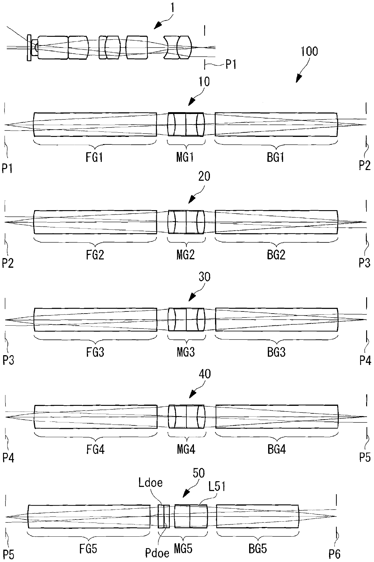
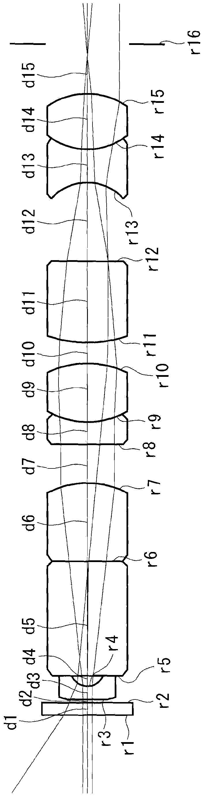
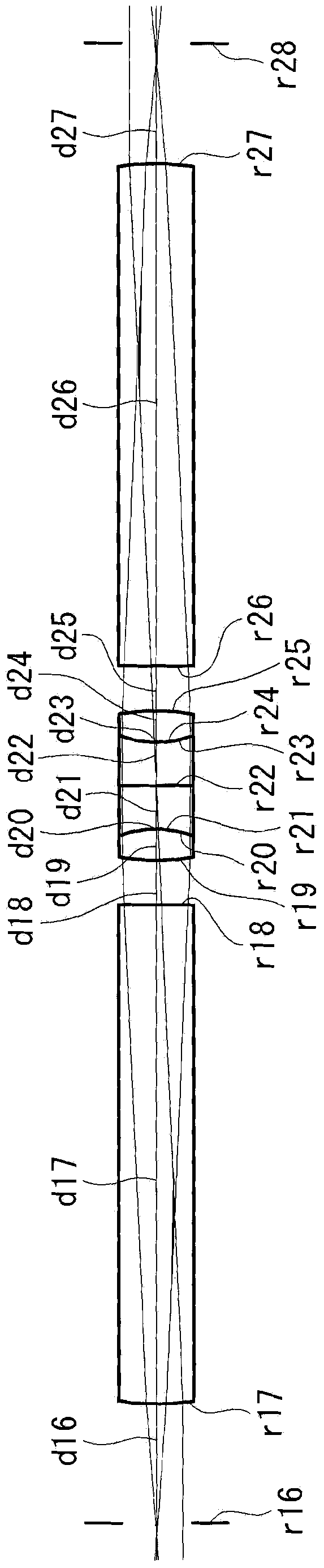
[0069] The optical system for rigid mirrors related to Embodiment 1 of the present invention is as follows: Figure 2 to Figure 7 As shown, an objective optical system and first to fifth relay optical systems are provided in this order from the object side.

[0070] The first to fourth relay optical systems include, in order from the object side, a positive front group consisting of a plano-convex lens with a convex surface facing the object side, a positive middle group consisting of a cemented lens, and a plano-convex lens having a convex surface facing the image side. Positive rear group formed. The fifth relay optical system includes, in order from the object side, a positive front group consisting of a plano-convex lens with a convex surface facing the object side, a positive middle group consisting of a diffractive optical element and a cemented lens, and a plano-convex lens with a convex surface facing the image side. Positive rear group composed of convex lens. The l...

Embodiment 2

[0082] The optical system for rigid mirrors related to Embodiment 2 of the present invention is as follows: Figure 9 and Figure 10 As shown, the lens structure of the objective optical system (face numbers 1 to 15) and the fifth relay optical system (face numbers 65 to 78) differs from the rigid mirror optical system of Example 1 mainly. In the fifth relay optical system, the diffractive optical element is sandwiched by two cemented lenses in the direction of the optical axis. The lens configurations of the first to fourth relay optical systems are substantially the same as those of the rigid mirror optical system of the first embodiment, and therefore illustration thereof is omitted. The lens data of the rigid mirror optical system according to this embodiment are as follows.

[0083] Figure 11 An axial chromatic aberration diagram of the rigid mirror optical system configured in this way is shown. According to the optical system for a rigid mirror of this embodiment, ...

Embodiment 3

[0093] The optical system for rigid mirrors related to Embodiment 3 of the present invention is as follows: Figure 12 As shown, the fifth relay optical system (surface numbers 65 to 78) is mainly different from the rigid mirror optical system of Example 2 in the lens structure. The lens configurations of the objective optical system and the first to fourth relay optical systems are substantially the same as those of the rigid mirror optical system of the second embodiment, and therefore illustration thereof is omitted. The lens data of the rigid mirror optical system according to this embodiment are as follows.

[0094] Figure 13 An axial chromatic aberration diagram of the rigid mirror optical system configured in this way is shown. According to the optical system for a rigid mirror of this embodiment, the axial chromatic image between the C-line (C-line) and the F-line (F-line) can be corrected by the cemented lens included in the first to fourth relay optical systems. Th...


PUM


Abstract

By suitably correcting a secondary spectrum, a clear, bright optical image is obtained. Provided is a rigid-scope optical system including: an objective optical system; and at least one relay optical systems that are formed of positive front groups, middle groups, and back groups in this order from an entrance side and that reimage an optical image imaged at imaging planes at the entrance side onto imaging planes at an exit side, wherein axial chromatic aberration between two wavelengths is corrected by an optical system other than the diffractive optical element, and axial chromatic aberration between the two wavelengths and another wavelength is corrected by the diffractive optical element.

Description

technical field [0001] The present invention relates to an optical system for a rigid endoscope and a rigid endoscope. Background technique [0002] Conventionally, as means for correcting axial chromatic aberration of an optical system included in a rigid endoscope, a diffractive optical element has been used in addition to a general cemented lens (for example, refer to Patent Document 1). [0003] Patent Document 1: Japanese Patent Application Laid-Open No. 8-29678 Contents of the invention [0004] The problem to be solved by the invention [0005] However, in the case of the optical system of Patent Document 1, the axial chromatic aberration between two wavelengths is corrected by the diffractive optical element, but there are axial chromatic aberrations of wavelengths other than these wavelengths that are not corrected as the so-called The secondary spectrum residues such a problem. In addition, since the lens structure is simple, there is a problem of low optical...

Claims


Application Information

Patent Timeline
Patent Type & Authority Applications(China)
IPC IPC(8): G02B13/00A61B1/00G02B13/18G02B13/24G02B23/26
CPCG02B27/42A61B1/0638A61B1/002A61B1/00163G02B23/243G02B23/2446G02B27/4211G02B27/0056
Inventor 井上贵博
Owner OLYMPUS CORP
Why Eureka
Try Eureka