A marking mechanism of a solar film thermal transfer marking machine

A thermal transfer printing and marking machine technology, applied in typewriters, printing, etc., can solve the problems of damaged marked items, failure to meet different needs of customers, and inability to place large blocks of engraved patterns, etc., to achieve the effect of ensuring normal use

Active Publication Date: 2015-11-25
苏州威仕薄膜科技有限公司
View PDF6 Cites 0 Cited by
  • Summary
  • Abstract
  • Description
  • Claims
  • Application Information

AI Technical Summary

Problems solved by technology

[0002] Existing carbon ribbon marking machines generally use pneumatic push to mark, but the pneumatic push uses a cylinder for push, which has a large impact force and the existing marking block is directly fixed on the push rod of the cylinder. Since the push rod of the cylinder pushes up and down for a certain distance, there must be a certain distance between the item to be marked and the marking block. When the item to be marked is too thick or too thin, the marked item will The distance between the marking block and the marking block is too large or too small, which will affect the marking effect, and the high impact force will easily damage the marked items
[0003] At the same time, the marking block of the existing marking machine is formed with three side-by-side elongated through grooves, which makes it possible to place only split-type multiple letter-shaped small blocks, and the general length and width of the small blocks are only 0.5. cm, but it is impossible to place some large blocks of engraved patterns on the rectangular upper plane, so that it can only print some letters and characters, and its marking is single, which cannot meet the different needs of customers.

Method used


Image

  • A marking mechanism of a solar film thermal transfer marking machine
  • A marking mechanism of a solar film thermal transfer marking machine
  • A marking mechanism of a solar film thermal transfer marking machine

Examples


Embodiment Construction

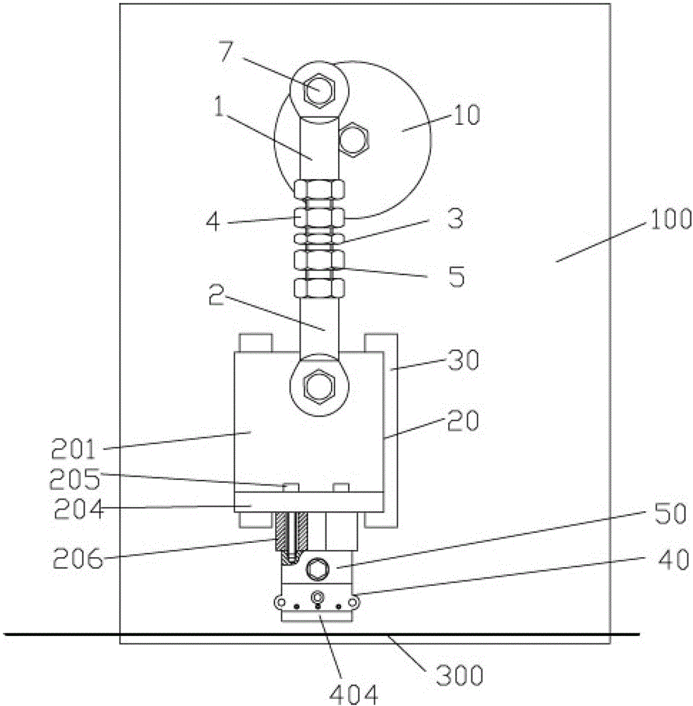
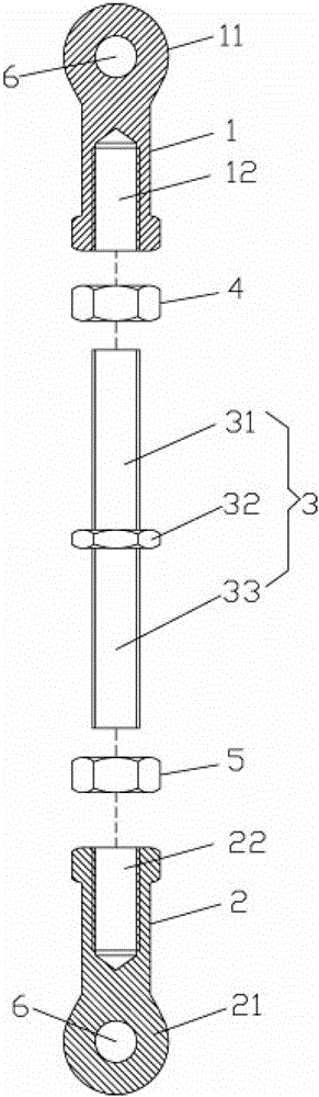
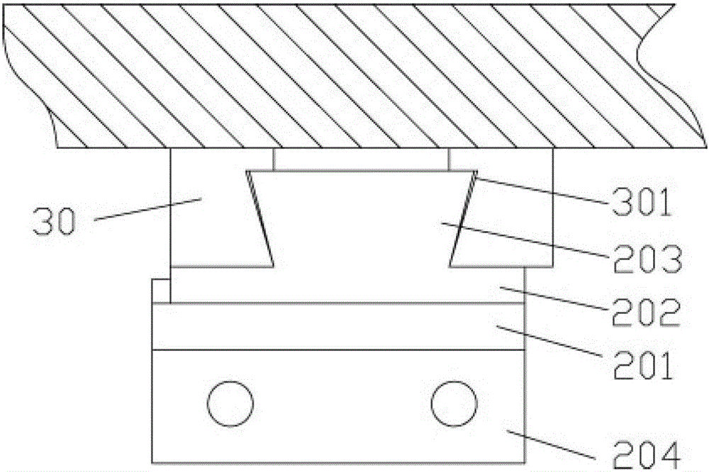
[0025] Examples, see e.g. Figures 1 to 8 As shown, a marking mechanism of a solar film thermal transfer marking machine includes a support plate 100 and a servo motor 200, the servo motor 200 is fixed on the back of the support plate 100, and the rotating shaft 2001 of the servo motor 200 is inserted into the support plate 100 Up and out the front of the support plate 100, the top of the rotating shaft 2001 is fixed with a rotating disk 10, the first oblate part 11 of the upper connection sleeve rod 1 of the telescopic device is fixed on the side of the rotating disk 10, the lower part of the telescopic device The second oblate part 21 of the connecting sleeve rod 2 is hinged on the sliding block 20, and the sliding block 20 is inserted into the sliding rail 30 fixed on the front of the support plate 100, and the bottom of the sliding block 20 is fixed with a heating block 50 for heating. A marking device 40 is fixed on the bottom surface of the block 50 , and the marking blo...


PUM


Abstract

The invention discloses a marking mechanism of a solar film thermal transfer printing marking machine. A servo motor is fixedly arranged on the back face of a supporting plate, a rotary shaft of the servo motor is inserted into the supporting plate in a sleeved mode and stretches out of the front face of the supporting plate, a rotary disc is fixedly arranged at the top end of the rotary shaft, the first oblateness portion of an upper connecting sleeve rod of a telescopic device is fixedly arranged on the side portion of the rotary disc, the second oblateness portion of a lower connecting sleeve rod of the telescopic device is hinged to a sliding block, the sliding block is inserted in a sliding rail fixedly arranged on the front face of the supporting plate in a sleeved mode, a heating block is fixedly arranged on the bottom portion of the sliding block, a marking device is fixedly arranged on the bottom face of the heating block, and the marking block of the marking device exactly faces the back face of a thermal transfer ribbon. The telescopic rod is driven by the rotary disc to push up and down, the sliding block fixedly arranged on the telescopic rod is made to vertically move, the marking block is made to carry out marking, the impact force of the marking mechanism is small, the telescopic rod can be fine adjusted, and therefore the requirements of various articles which have different thicknesses and need to be marked can be met.

Description

Technical field: [0001] The invention relates to the technical field of marking machine equipment, and more specifically relates to a marking mechanism of a solar film thermal transfer marking machine. Background technique: [0002] Existing carbon ribbon marking machines generally use pneumatic push to mark, but the pneumatic push uses a cylinder for push, which has a large impact force and the existing marking block is directly fixed on the push rod of the cylinder. Since the push rod of the cylinder pushes up and down for a certain distance, there must be a certain distance between the item to be marked and the marking block. When the item to be marked is too thick or too thin, the marked item will If the distance from the marking block is too large or too small, it will affect the marking effect, and the impact force will easily damage the marked items. [0003] At the same time, the marking block of the existing marking machine is formed with three side-by-side elongat...

Claims


Application Information

Patent Timeline
Patent Type & Authority Patents(China)
IPC IPC(8): B41J2/315B41J3/407
Inventor 孙加元
Owner 苏州威仕薄膜科技有限公司
Why Eureka
Try Eureka