Electronic lock system and control method thereof

The technology of an electronic lock system and control method is applied to building locks, non-mechanical transmission-operated locks, buildings, etc., which can solve the problems of standby power consumption and keeping the closed state, etc., to reduce pressure, ensure reliability, and have strong adaptability Effect

Inactive Publication Date: 2013-11-06
WUHAN PULINGUANGTONG TECH
View PDF5 Cites 5 Cited by
  • Summary
  • Abstract
  • Description
  • Claims
  • Application Information

AI Technical Summary

Problems solved by technology

[0009] The present invention aims at the defects existing in the existing technical solutions, and provides an electronic lock system and its control method, which can use the electronic door latch (1) and the mechanical hook 2 to lock when the electronic lock system is in the daily power-off state, so that the electronic lock system It remains closed, which not only solves the problem of standby power consumption, but also ensures the security of the electronic lock system

Method used


Image

  • Electronic lock system and control method thereof
  • Electronic lock system and control method thereof
  • Electronic lock system and control method thereof

Examples


Embodiment 1

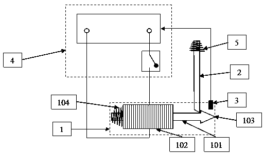
[0037] Embodiment 1. An electronic lock system. When the electronic lock system is closed, the electronic door latch and the mechanical hook are kept locked, as shown in Figure (1), wherein:

[0038] The electronic door latch (1) has the function of closing after power-on, recovering and keeping open after power-off; it is used to close the electronic lock system when it is closed; and to open the electronic lock system after it is opened;

[0039] The mechanical hook (2) is used for interlocking with the electronic door latch when the electronic lock system is closed, and can be unlocked under the action of external force;

[0040] The sensor (3) is used to sense whether the electronic door latch and the mechanical hook are kept or unlocked, and is connected to the power supply control unit;

[0041] The power supply control unit (4) is used to control the power supply to the electronic door latch; it is responsible for disconnecting the power supply circuit to the electronic...

Embodiment 2

[0072] Embodiment 2. An electronic lock system. The difference between the electronic lock system of this embodiment and Embodiment 1 is that

[0073] The electronic door latch includes an electric suction iron (106), an access control iron block (107), and a hook (103). The electric absorption iron is responsible for attracting the access control iron block when it is powered on, and controls the electronic lock system to be in a locked state; The hook is responsible for keeping locked with the mechanical hook, and controls the electronic lock to be in the closed state.

[0074] As shown in Figure (11), it is a structural schematic diagram of the locking hook and the mechanical hook when the electronic lock system is closed. Wherein, the electric suction iron and the access control iron block are respectively installed on the door frame and the door panel. When the door is closed, the power supply control unit (4) disconnects the power supply line to the electric suction iro...

Embodiment 3

[0078] Embodiment three, the control method of electronic lock system, it is characterized in that:

[0079] A1. When the electronic lock system is in the closed state, the electronic door latch and the mechanical hook are locked to each other, and the power supply control unit disconnects the power supply circuit to the electronic door latch;


PUM


Abstract

The embodiment of the invention provides an electronic lock system and a control method thereof. The electronic lock system comprises an electronic latch (1), a mechanical hook (2), an inductor (3) and a power supply control unit (4). The electronic lock system and the control method of the electronic lock system have the advantages of enabling the electronic lock system to be still maintained in a closed state due to the fact that the mechanical hook (2) and the electronic latch (1) are locked under the daily power-off state, greatly reducing pressure on a power supply system under the condition that reliability and security of the electronic lock system are guaranteed and being low in requirement for using occasions, strong in adaptability and beneficial to popularization and application of the type of electronic door lock products.

Description

technical field [0001] The invention relates to the technical field of security control, in particular to an electronic lock system and a control method thereof. [0002] Background technique [0003] Electronic door lock systems have been used in many fields, such as electronic access control systems in the field of security control, cabinet access control systems in the field of automatic control, etc. Electronic door lock systems have already existed as an indispensable method. [0004] Traditional electronic door lock systems often use the following two methods: [0005] (1) Control and manage the electromagnetic gate valve that remains closed after power-on and opens after power-off. This type of system requires continuous power supply, has a large power consumption, and is affected by the power system, resulting in poor stability and reliability; [0006] (2) Control and manage the electromagnetic gate valve that remains closed after power failure and opens when powe...

Claims


Application Information

Patent Timeline
Patent Type & Authority Applications(China)
IPC IPC(8): E05B47/00
Inventor 徐志国
Owner WUHAN PULINGUANGTONG TECH
Why Eureka
Try Eureka