Electromagnetic heating welding method for thermoplastic pipes

A thermoplastic and electromagnetic induction heating technology, which is applied in the direction of pipeline connection layout, pipes/pipe joints/fittings, mechanical equipment, etc., can solve the problems of high labor costs and pipes that cannot be exposed to the air for a long time, so as to reduce labor costs, The effect of maintaining strength and improving efficiency

Inactive Publication Date: 2013-11-06
TIANJIN JUNXING PIPE GRP CO LTD
View PDF8 Cites 18 Cited by
  • Summary
  • Abstract
  • Description
  • Claims
  • Application Information

AI Technical Summary

Problems solved by technology

[0007] The invention designs a thermoplastic pipe electromagnetic heating welding method, which solves the technical problems: (1) The speed of pipe heating is much faster than the speed of pipe insertion, and the heated pipe cannot be exposed to the air for a long time , so that requires more labor expenditure

Method used


Image

  • Electromagnetic heating welding method for thermoplastic pipes
  • Electromagnetic heating welding method for thermoplastic pipes
  • Electromagnetic heating welding method for thermoplastic pipes

Examples


Embodiment 1

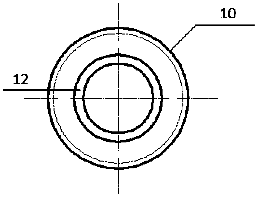
[0025] Such as figure 1 As shown, an annular metal mesh layer 12 is provided on the inner wall of the plastic connector 10, and the metal mesh layer 12 converts electromagnetic energy into heat energy and makes the junction of two thermoplastic pipes thermally fused.

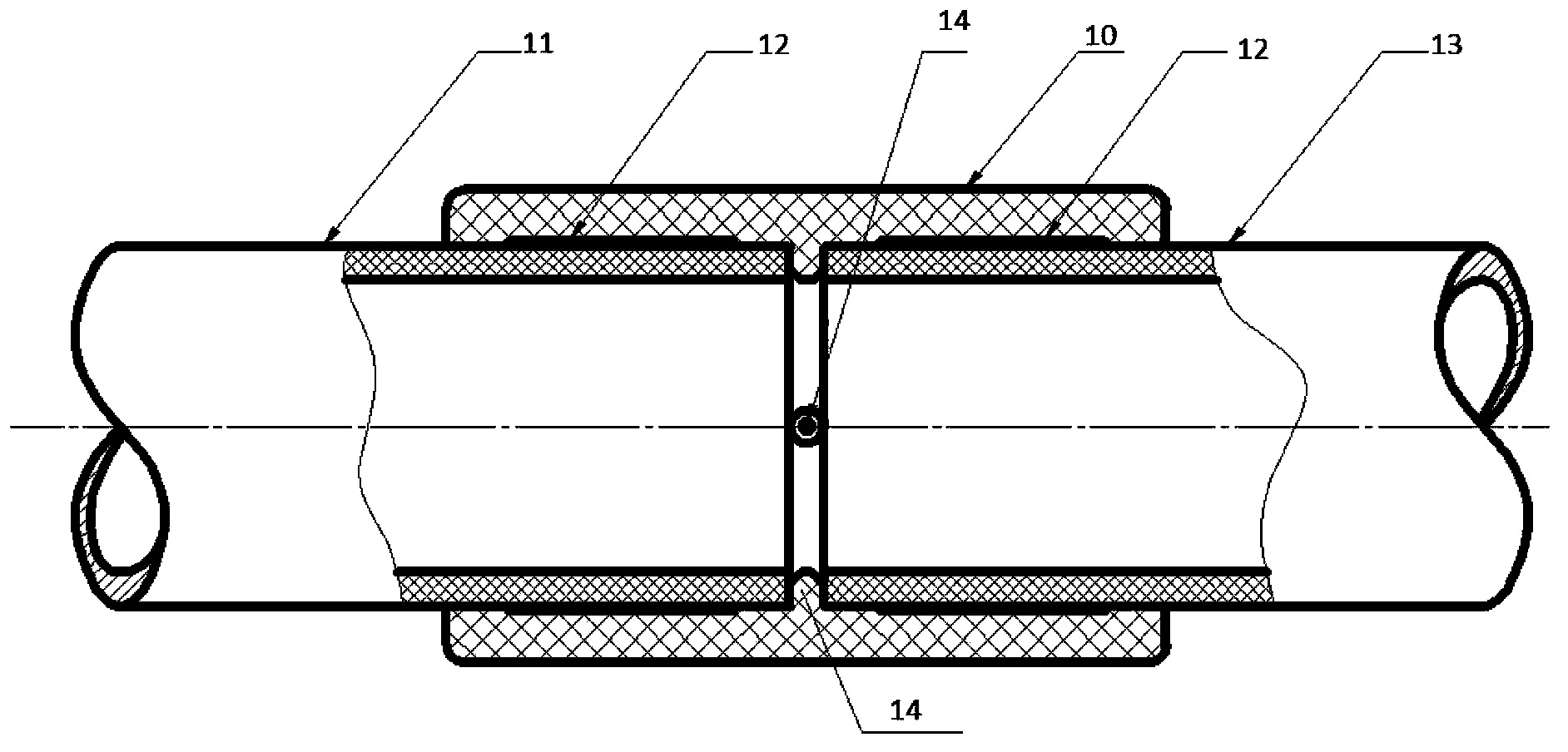
[0026] Such as figure 2 As shown, the two thermoplastic pipes are thermoplastic pipe A11 and thermoplastic pipe B13 respectively, and the thermoplastic pipe B13 and thermoplastic pipe A11 are respectively inserted into the two ends of the plastic connector 10, and the metal mesh layer 12 is fixed on the inner wall of the plastic connector 10 superior.

[0027] The inner wall of the plastic connector 10 is also provided with positioning pins 14 to limit the insertion positions of the thermoplastic pipe B13 and the thermoplastic pipe A11 .

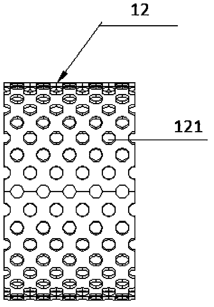
[0028] Such as image 3 As shown, the metal mesh layer 12 is provided with a lot of mesh holes 121, the metal mesh layer 12 generates heat and makes the hot-melted pipe pa...

Embodiment 2

[0031] Such as Figure 4 As shown, the steel-plastic composite pipe 2 includes an outer plastic layer 21 , a first glued layer 22 , a metal layer 23 , a second glued layer 24 and an inner plastic layer 25 from outside to inside. The present invention utilizes the metal layer 23 in the existing structure of the steel-plastic composite pipe 2 to convert electromagnetic energy into thermal energy through the metal layer 22 and make the junction of two steel-plastic composite pipes 2 thermally fused.

[0032] Such as Figure 5 and Figure 6 As shown, two steel-plastic composite pipes 2 need to be connected by a plastic connector 4. The plastic connector 4 is a columnar structure, which includes a cavity 43 and an outer wall 44. The cavity 43 connects the two steel-plastic composite pipes 2 To communicate, the outer wall 44 is connected to the electromagnetic heater.

[0033] One end of the plastic connector 4 is provided with a left annular slot 41, and a steel-plastic composit...


PUM


Abstract

The invention relates to a heating welding method for thermoplastic pipes. The method comprises the steps of Step 1, forming a metal mesh layer (12) on the inner wall of a plastic connecting piece (10); Step 2, performing inserting connection on the two thermoplastic pipes and the plastic connecting piece, and performing centering and positioning through positioning pins (14) in the plastic connecting piece; Step 3, sleeving an electromagnetic induction heating coil on the plastic connecting piece (10), and performing energization for heating; Step 4, performing heating till the two thermoplastic pipes and the plastic connecting piece are welded fully, and then performing deenergization; Step 5, performing cooling shaping. According to the method, the thermoplastic pipes or steel-plastic composites pipes are connected through the plastic connecting piece in advance and then fixed through electromagnetic heating hot melting, so that the traditional mode of heating before inserting connection is changed, the connection efficiency is improved, and meanwhile, the labor cost is reduced.

Description

technical field [0001] The invention relates to a method for heating and welding plastic pipes, in particular to an electromagnetic heating and welding method for thermoplastic pipes or steel-plastic composite pipes. Background technique [0002] Thermoplastic pipes are high-tech composite chemical building materials, and chemical building materials are the fourth largest category of new building materials in the contemporary era after steel, wood, and cement. Chemical building materials have made great progress and developed rapidly in our country, especially the widespread use of new environmentally friendly plastic pipes, which has set off a revolution to replace traditional building materials. Plastic pipes are widely used in the fields of building water supply and drainage, urban water supply and drainage, and gas pipes because of their advantages such as small water loss, energy saving, material saving, ecological protection, and convenient completion. They have become...

Claims


Application Information

Patent Timeline
Patent Type & Authority Applications(China)
IPC IPC(8): F16L47/03
CPCB29C66/5221B29C65/364B29C65/3648B29C65/3656B29C65/3676B29C65/368B29C65/7829B29C65/7832B29C65/7835B29C66/1122B29C66/1222B29C66/1224B29C66/12441B29C66/52291B29C66/52292B29C66/72321
Inventor 夏成文梁增红赵满超韩英民吴晓芬
Owner TIANJIN JUNXING PIPE GRP CO LTD
Why Eureka
Try Eureka