Motor control device and electric power steering device

A motor control and motor technology, which is applied in the field of electric power steering devices, can solve the problems of larger occupied area of ​​the substrate, larger substrate size, difficulty in realizing wiring resistance, etc., and achieve the effect of suppressing torque fluctuations

Inactive Publication Date: 2013-11-06
JTEKT CORP
View PDF10 Cites 4 Cited by
  • Summary
  • Abstract
  • Description
  • Claims
  • Application Information

AI Technical Summary

Problems solved by technology

[0016] However, if the wiring pattern is formed so as to sufficiently reduce the torque ripple, the circuit pattern in the above-mentioned motor drive circuit board becomes complicated, and the space for forming the circuit pattern increases.
That is, in the motor drive circuit board, although the wiring pattern can be designed so that the wiring resistance of the path from the power supply terminal to the ground terminal is consistent between phases, it is difficult to achieve a sufficient reduction in the wiring resistance so that it does not affect the motor drive. degree, the switching elements constituting the motor drive circuit are arranged symmetrically
Therefore, if the resistance component from the power supply terminal to the output terminal of the motor drive circuit (hereinafter referred to as "upper arm resistance") is the same as the resistance component from the output terminal to the ground terminal (hereinafter referred to as "lower arm resistance") When the wiring pattern is formed in this way, the circuit pattern becomes complicated, and a large space is required for forming the circuit pattern, and the size of the substrate increases.
As a result, in the electric power steering device, the area occupied by the board in the ECU becomes large, which violates the above-mentioned request for miniaturization, etc.

Method used


Image

  • Motor control device and electric power steering device
  • Motor control device and electric power steering device
  • Motor control device and electric power steering device

Examples


no. 1 approach )

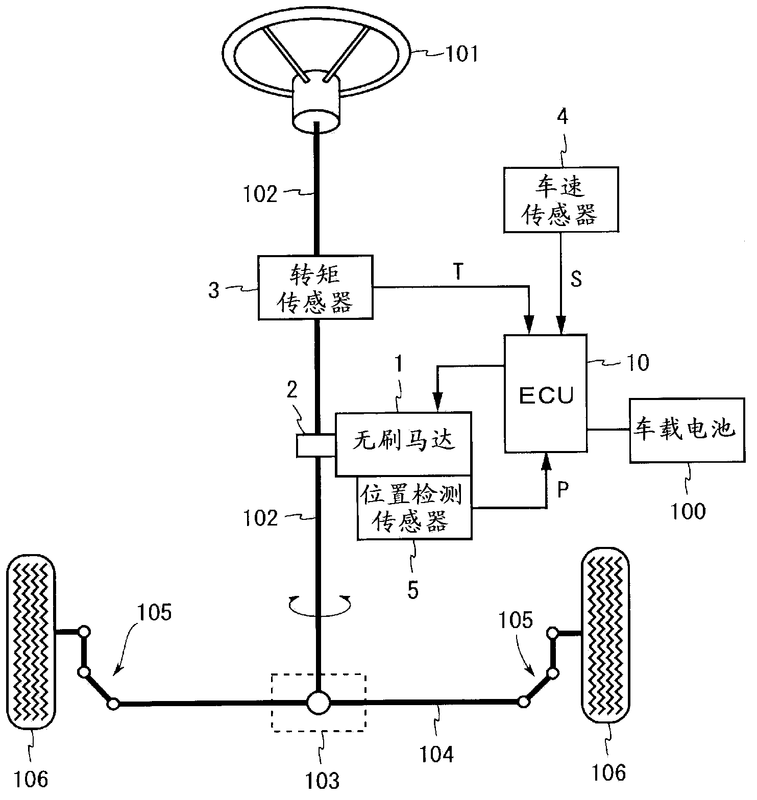
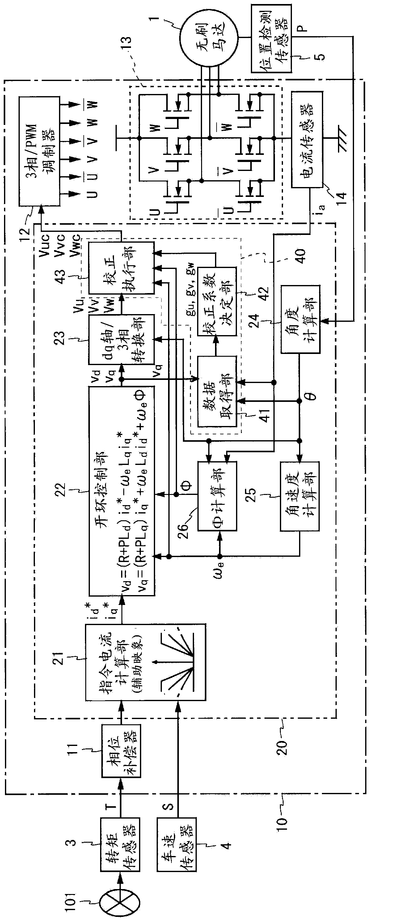
[0114] figure 2 It is a block diagram showing the configuration of the motor control device according to the first embodiment of the present invention. figure 2 The illustrated motor control device is configured using an ECU 10 and drives a brushless motor 1 having three-phase windings (not shown) of u-phase, v-phase, and w-phase. The ECU 10 includes a phase compensator 11 , a microcomputer 20 , a 3-phase / PWM (Pulse Width Modulation, pulse width modulation) modulator 12 , a motor drive circuit 13 , and a current sensor 14 .

[0115] The steering torque T output from the torque sensor 3 , the vehicle speed S output from the vehicle speed sensor 4 , and the rotational position P output from the position detection sensor 5 are input to the ECU 10 . The phase compensator 11 performs phase compensation for the steering torque T. The microcomputer 20 functions as a control unit for obtaining a voltage command value used for driving the brushless motor 1 . Details of the functio...

no. 2 approach >

[0195] Figure 8 It is a block diagram showing the configuration of a motor control device according to a second embodiment of the present invention. In the motor control device of the present embodiment, the microcomputer 20 and the current sensor 14 are replaced with the microcomputer 30 and the current sensor 15 in the motor control device of the first embodiment. This motor control device performs feedback control when the current sensor 15 is operating normally, and performs open-loop control when the current sensor 15 fails.

[0196] One current sensor 15 is provided on each of the paths through which the three-phase drive currents supplied to the brushless motor 1 flow, and detects the three-phase drive currents. The current values ​​of the three phases detected by the current sensor 15 (hereinafter referred to as u-phase current detection value i u , V-phase current detection value i v And w-phase current detection value i w ) is input to the microcomputer 30.

[...

no. 3 approach >

[0220] refer to Figure 9 to Figure 11 Next, a motor control device according to a third embodiment of the present invention will be described.

[0221] Among them, the main difference between the third embodiment and the first embodiment is as follows: Instead of the data acquisition unit 41, the correction coefficient determination unit 42, and the correction execution unit 43 of the first embodiment, the phase current calculation unit 141 is implemented by a microcomputer. , the storage unit 142 , the phase resistance calculation unit 143 and the functions of the correction unit 144 . In the following description, the same reference numerals are assigned to the same configurations as those of the first embodiment, and description thereof will be omitted.

[0222] In the present embodiment, the current sensor 14 and the phase current calculation unit 41 described later are configured to detect the current I of the u-phase, v-phase, and w-phase of the brushless motor 1 . u ...


PUM


Abstract

An open loop control unit obtains voltage instruction values v d and v q on dq-axes based on current instruction values i d * and i q * on the dq-axes, an armature winding interlinking magnetic flux number ¦, and the angular velocity É e of a rotor in a motor, and a dq-axis / 3-phase conversion unit converts the voltage instruction values v d , and v q into phase voltage instruction values V u , V v , and V w . On the other hand, a data acquisition unit acquires angle-dependent data showing the dependency of a secondary harmonic component concerning the electric angle of the d-axis or q-axis component of the motor current on the electric angle, based on the current detection value i a and the electric angle ¸, and a correction coefficient determination unit determines correction coefficients for correcting the phase voltage instruction values so as to reduce the dependency based on the angle-dependent data. A correction execution unit corrects the phase voltage instruction values V u , V v , and V w obtained by the dq-axis / 3-phase conversion unit, based on the determined correction coefficients.

Description

[0001] This application is a divisional application of the PCT application with the application number 200980102108.9, the date of entering the Chinese national phase is July 13, 2010, and the title of the invention is "motor control device and electric power steering device". technical field [0002] The present invention relates to a motor control device for driving a brushless motor and an electric power steering device having such a motor control device. Background technique [0003] Conventionally, an electric power steering apparatus is used that drives an electric motor in response to a steering torque applied by a driver to a handle (steering wheel) to impart steering assist force to a steering mechanism of a vehicle. Conventionally, brushed motors have been widely used as electric motors for electric power steering devices, but in recent years, brushless motors have also been used from the viewpoint of improvement in reliability and durability, reduction in inertia, ...

Claims


Application Information

Patent Timeline
Patent Type & Authority Applications(China)
IPC IPC(8): H02P21/06B62D5/04
CPCB62D5/0463H02P21/06B62D5/046H02P6/10H02P21/00
Inventor 上田武史内田修弘吉田航也
Owner JTEKT CORP
Why Eureka
Try Eureka