Rotary foaming mold frame

A foaming mold, rotary technology, applied in the field of foaming mold frame, can solve the problems of limited flip angle, inaccurate repeating angle, unable to adjust the angle, etc. Effect

Active Publication Date: 2015-04-15
宁波万众汽车零部件有限公司
View PDF4 Cites 0 Cited by
  • Summary
  • Abstract
  • Description
  • Claims
  • Application Information

AI Technical Summary

Problems solved by technology

[0002] The existing foaming mold frame uses a rotary cylinder to turn the mold, and the turning angle is limited, and the angle cannot be adjusted at will according to the needs. In the case of a special angle adjustment, the requirement cannot be realized, resulting in poor foaming quality of the product. Moreover, the repeating angle of the existing foaming mold frame is inaccurate

Method used


Image

  • Rotary foaming mold frame
  • Rotary foaming mold frame
  • Rotary foaming mold frame

Examples


Embodiment Construction

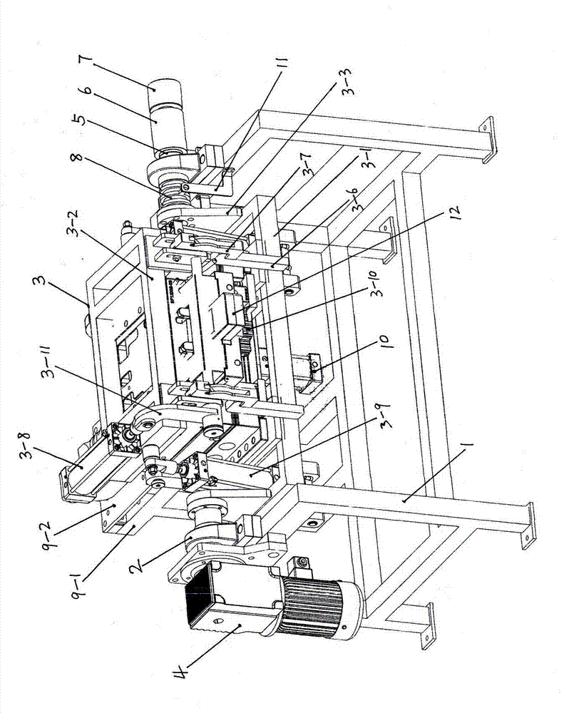
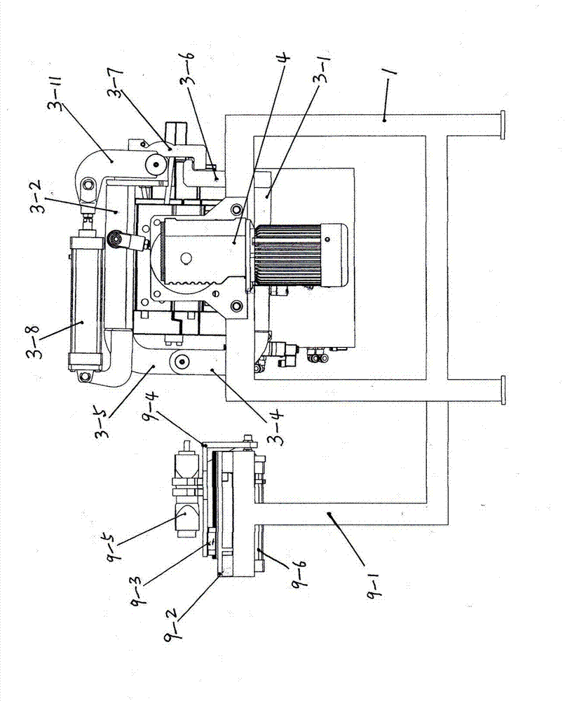
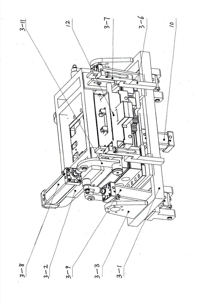
[0015] refer to figure 1 —6, it includes the main frame 1, the bearing housing 2 is fixed on both sides of the upper part of the main frame; there is also a rotating mechanism 3, the rotating mechanism includes the lower frame 3-1 and the upper frame 3-2, and the lower frame both sides are provided with connections Plate 3-3, one end of the lower frame is connected with the lower hinge 3-4, one end of the upper frame is connected with the upper hinge 3-5, the upper and lower hinges are corresponding and connected by hinge shafts, the other end of the lower frame is connected with the lower lock Tight hook 3-6, the other end of the upper frame is connected with the upper locking hook 3-7, the upper frame is fixed with the locking cylinder 3-8, the cylinder rod end of the locking cylinder is connected with the pin shaft and the locking arm 3- One end of 11 is connected, and the other end of the locking arm is welded with a shaft sleeve 3-12, and a locking shaft 3-13 is arranged ...


PUM


Abstract

The invention discloses a rotary foaming mold frame, relates to a rotatable foaming mold frame, and mainly aims to solve the problems of limited overturning angle of an existing foaming mold frame and the like. The rotary foaming mold frame comprises a main frame, bearing seats and a material injection mechanism, wherein a rotary mechanism comprises a lower frame and an upper frame; the lower frame is provided with connection plates; a lower hinge is connected with an upper hinge through a hinge shaft; a lower locking hook and an upper locking hook are arranged on the lower frame and the upper frame respectively; a cylinder rod of a locking air cylinder is connected with a locking arm; a locking shaft is arranged in a shaft sleeve of the locking arm; a limiting seat comprises two vertical plates; the locking shaft penetrates through the two vertical plates; a shaft hole of a swinging block is sleeved in the locking shaft; holes are formed in the two vertical plates; connection sheets are arranged between the two vertical plates; the swinging block is connected with the connection sheets; a limiting pin shaft on the swinging block is in contact with the locking hook; a mold opening and closing air cylinder is arranged on the lower frame; a material sealing air cylinder is arranged on a mold; ejection air cylinders are arranged on the lower frame; a transmission shaft of a motor speed reducer is connected with the connection plates; an air water separator, a conductive sliding ring and a sensor induction block are arranged on an air water separator shaft. The rotary foaming mold frame has the advantage that an angle can be randomly adjusted.

Description

Technical field: [0001] The invention relates to a rotatable foam mold frame. Background technique: [0002] The existing foaming mold rack uses a rotating cylinder to turn the mold, and the turning angle is limited, and the angle cannot be adjusted at will according to the needs. In the case of a special angle adjustment, the requirement cannot be realized, resulting in poor foaming quality of the product. Moreover, the repeating angle of the existing foaming mold frame is inaccurate. Invention content: [0003] The technical problem to be solved by the present invention is to provide a rotary foaming mold frame which can adjust the angle freely and repeat the angle accurately. [0004] The above-mentioned purpose is achieved in this way: it includes a main frame, and bearing seats are fixed on both sides of the upper part of the main frame; One end is connected with the lower hinge, one end of the upper frame is connected with the upper hinge, the upper and lower hinge...

Claims


Application Information

Patent Timeline
Patent Type & Authority Patents(China)
IPC IPC(8): B29C44/60B29C44/58
Inventor 韩国跃王秀峰吴岩高坡刘宁宁
Owner 宁波万众汽车零部件有限公司
Why Eureka
Try Eureka