Volume pump for liquid

A volumetric and liquid technology, which is applied in the direction of liquid displacement machines, pumps, pumps with flexible working elements, etc., can solve the problem of insufficient pressure drop in the pump chamber, improper operation of the check valve on the suction side, and check valve on the discharge side. The valve is not working properly (the valve core is not displaced to the open valve position, etc., to achieve the effect of good pump function

Inactive Publication Date: 2013-11-13
NIPPON PILLAR PACKING CO LTD +1
View PDF7 Cites 9 Cited by
  • Summary
  • Abstract
  • Description
  • Claims
  • Application Information

AI Technical Summary

Problems solved by technology

Therefore, if there are large air bubbles in the pump chamber, the air bubbles are only compressed in the discharge process, the pump chamber is not substantially shrunk, the pressure rise in the pump chamber is not sufficient, and the discharge side check valve does not work properly (the valve core does not move toward the open position). valve position displacement), in addition, in the suction process, only the bubble expands, the pump chamber does not expand substantially, the pressure drop in the pump chamber is insufficient, and the suction side check valve does not work properly (the valve core does not move to the valve open position ) such a so-called air lock phenomenon
In addition, even if the bubbles generated or retained in the pump chamber are small or small in one step, the bubbles will gradually increase and become huge due to repeated steps, and there is a possibility of the above-mentioned air lock phenomenon.

Method used


Image

  • Volume pump for liquid
  • Volume pump for liquid
  • Volume pump for liquid

Examples


Embodiment Construction

[0028] Based on the drawings, the method for implementing the present invention will be described in detail.

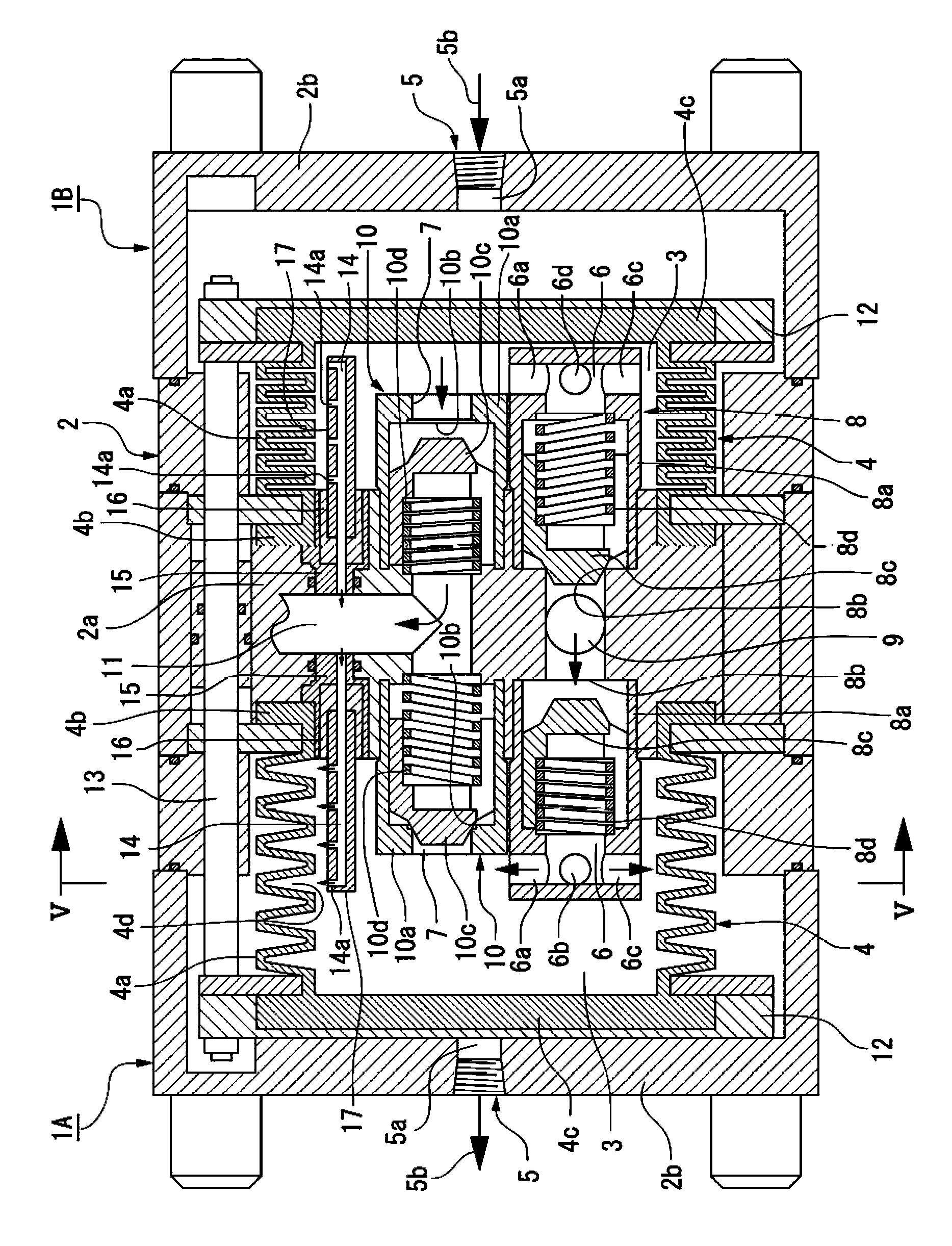
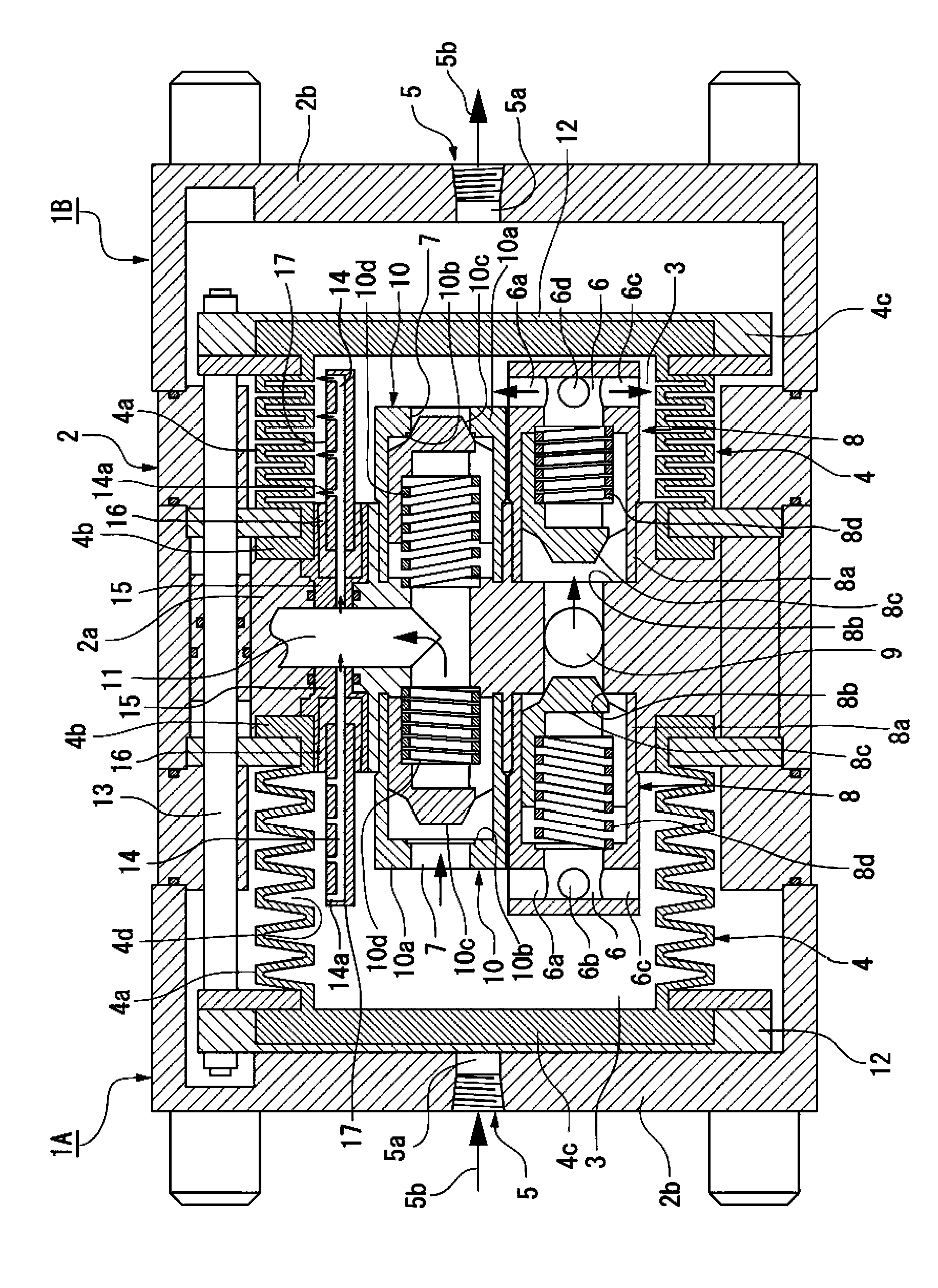
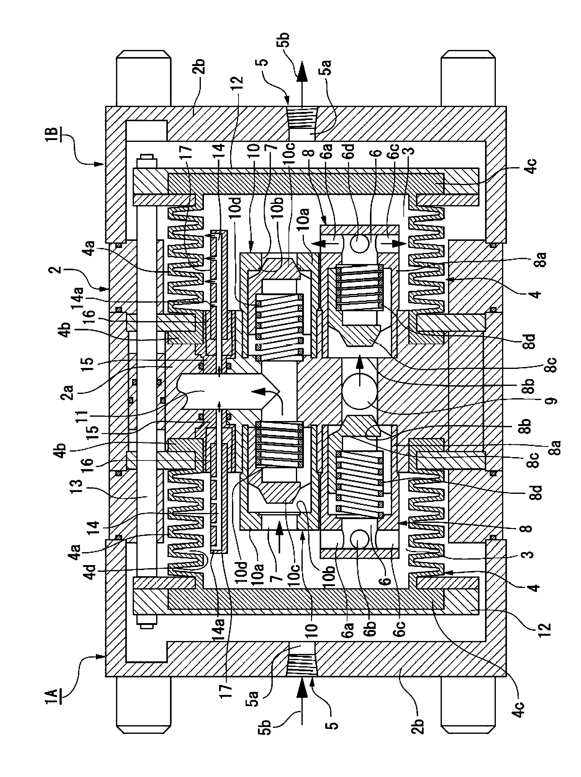
[0029] figure 1 It is a longitudinal sectional side view showing an example of a liquid delivery pump equipped with a positive displacement pump for liquid of the present invention, figure 2 as well as image 3 Respectively represent and figure 1 Different state of action and figure 1 Equivalent longitudinal side view, Figure 4 Is to figure 1 The main part of the zoomed in to show the details, Figure 5 Is along figure 1 A vertical sectional front view of the main part of the V-V line. In addition, in the following description, up and down, left and right refer to Figure 1 ~ Figure 3 Up and down, left and right.

[0030] figure 1 The liquid delivery pump shown is used for liquids that tend to retain bubbles in the pump (for example, foaming liquids such as ozone water, hydrogen peroxide water, etc., which contain bubbles due to high temperature, high pressure, cavitation...


PUM


Abstract

The invention discloses a volume pump for liquid. In the invention, the volume pump for liquid is formed in a mode of alternately and continuously carrying out a suction process of supplying the liquid to a pump chamber (3) from a suction passage (9) through a check valve (8) at the suction side and a suction port (6) by enlarging the volume of the pump chamber (3) and a discharge process of feeding the liquid to a discharge passage (9) from the pump chamber (3) through a discharge port (7) and a check valve (10) at the discharge side by reducing the volume of the pump chamber (3); and in a pump for processing the liquid which generates bubbles in the pump chamber (3), the volume pump for liquid is formed in a mode that an upper region of the pump chamber (3) is directly communicated and connected with the discharge passage (9) by a pore passage (14) and the liquid in the pump chamber (3) is enabled to slightly flow towards the discharge passage (9) from the pore passage (14) in the discharge process so as to remove the bubbles in the pump chamber (3) and enable the check valves (8, 10) not to generate the gas locking phenomenon.

Description

Technical field [0001] The present invention relates to volumetric pumps such as bellows pumps used as liquid delivery pumps in the semiconductor and liquid crystal markets, etc., and in particular to foaming liquids (for example, ozone water, hydrogen peroxide water, etc.) ), a positive displacement pump for liquids containing bubbles (for example, liquids that generate bubbles due to high temperature, high pressure, cavitation, etc.). Background technique [0002] As a conventional positive displacement pump for liquids, it is generally known to have a pump chamber surrounded by a telescopic bellows and configured to expand and contract the volume, a suction port and a discharge port that open in the pump chamber, and a pump chamber through the suction side. The suction passage connected to the suction port by the check valve, and the discharge passage connected to the discharge port via the discharge side check valve are alternately and continuously performed by expanding the ...

Claims


Application Information

Patent Timeline
Patent Type & Authority Applications(China)
IPC IPC(8): F04B43/08
Inventor 野边田政宪藤井达也元村智博森山优一
Owner NIPPON PILLAR PACKING CO LTD
Why Eureka
Try Eureka