A method, terminal and network equipment for performing carrier aggregation

A carrier aggregation and carrier technology, applied in digital transmission systems, error prevention, electrical components, etc., can solve problems such as wasted subframes, terminals ignore base station scheduling, etc., and achieve the effect of avoiding scheduling errors

Inactive Publication Date: 2018-03-23
ZTE CORP
View PDF4 Cites 0 Cited by
  • Summary
  • Abstract
  • Description
  • Claims
  • Application Information

AI Technical Summary

Problems solved by technology

In the subsequent stage of carrier aggregation, TDD carriers with different uplink and downlink configurations are supported for aggregation. At this time, the terminal often ignores the scheduling of the base station, or the problem of wasting subframes

Method used


Image

  • A method, terminal and network equipment for performing carrier aggregation
  • A method, terminal and network equipment for performing carrier aggregation
  • A method, terminal and network equipment for performing carrier aggregation

Examples


Embodiment 1

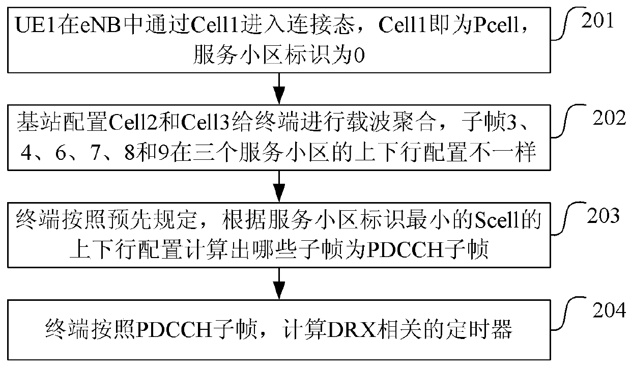
[0041] Such as figure 2 As shown, the method for performing carrier aggregation in this embodiment includes:

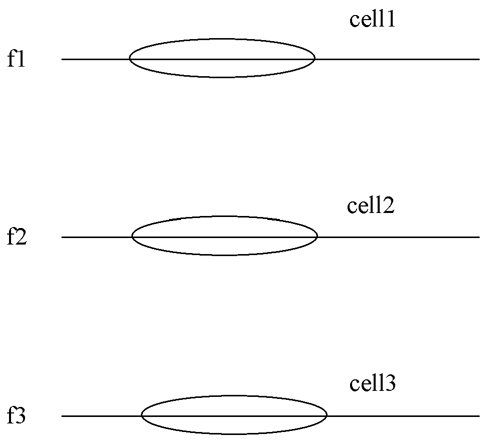
[0042]Step 201: UE1 enters the connected state through Cell1 in the eNB, Cell1 is the Pcell, and the serving cell ID is 0;

[0043] Step 202: Due to the increase in traffic, the base station configures Cell2 and Cell3 for the terminal to perform carrier aggregation. Cell2 is a Scell, and the serving cell ID is set to 1. Cell3 is also a Scell, and the serving cell ID is set to 2. It can be seen from Table 0-1 , the uplink and downlink configurations of subframes 3, 4, 6, 7, 8 and 9 in the three serving cells are different;

[0044] Step 203: The terminal calculates which subframes are PDCCH subframes according to the uplink and downlink configuration of Cell2 according to the Scell ​​with the smallest serving cell identifier, that is, in the uplink and downlink configuration of Cell2, the downlink subframes or the subframes containing DwPTS The frame is a PDCCH subf...

Embodiment 2

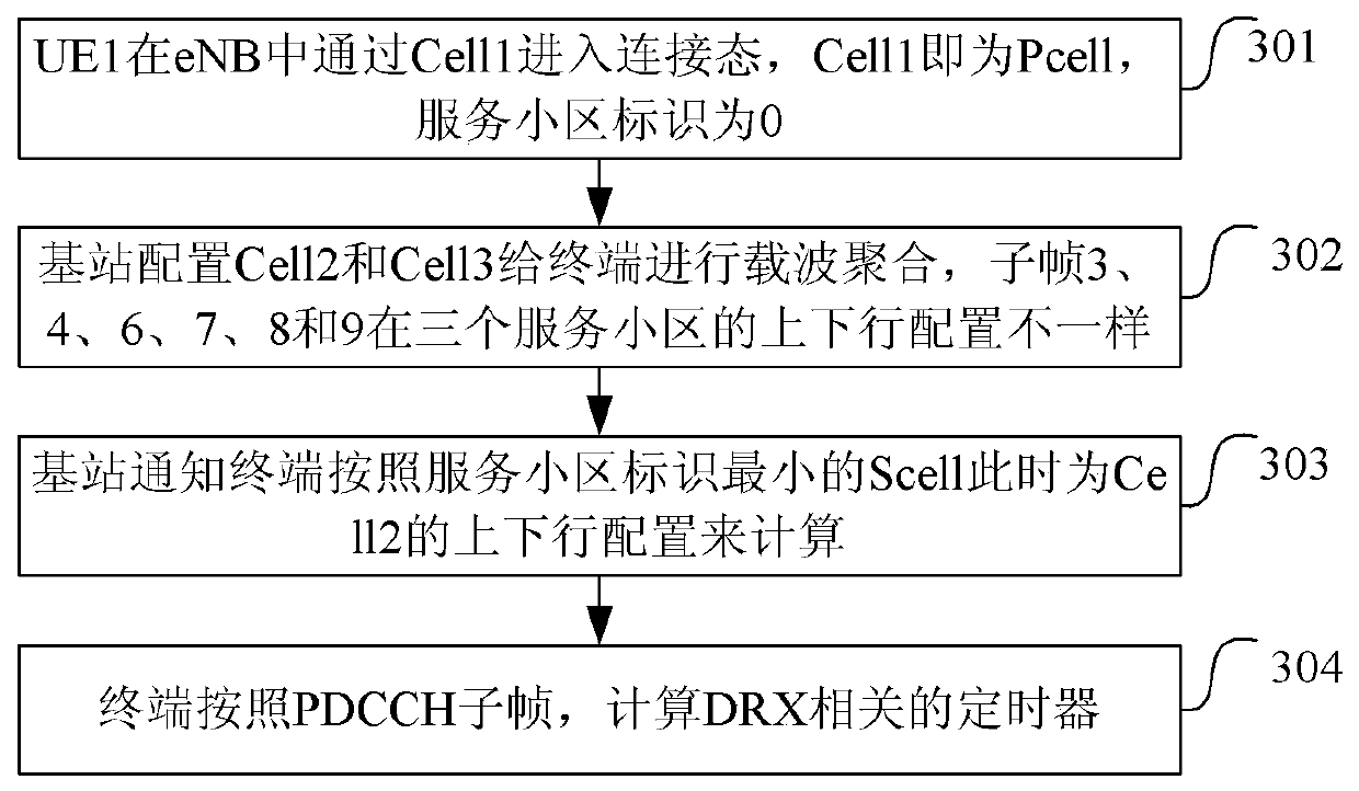
[0052] Such as image 3 As shown, the method for performing carrier aggregation in this embodiment includes:

[0053] Step 301: UE1 enters the connected state through Cell1 in the eNB, Cell1 is the Pcell, and the serving cell ID is 0;

[0054] Step 302: Due to the increase in traffic volume, the base station configures Cell2 and Cell3 for the terminal to perform carrier aggregation. Cell2 is a Scell, and the serving cell ID is set to 1. Cell3 is also a Scell, and the serving cell ID is set to 2. It can be seen from Table 0-1 , the uplink and downlink configurations of subframes 3, 4, 6, 7, 8 and 9 in the three serving cells are different;

[0055] Step 303: The base station notifies the terminal to calculate the uplink and downlink configuration of Cell2 according to the Scell ​​with the smallest serving cell identifier at this time, that is, in the uplink and downlink configuration of Cell2, the downlink subframe or the subframe containing DwPTS is a PDCCH subframe, and the ...

Embodiment 3

[0065] Such as Figure 4 As shown, the method for performing carrier aggregation in this embodiment includes:

[0066] Step 401: UE1 enters the connection state through Cell1 in the eNB, Cell1 is the Pcell, and the serving cell ID is 0;

[0067] Step 402: Due to the increase in traffic volume, the base station configures Cell2 and Cell3 for the terminal to perform carrier aggregation. Cell2 is a Scell, and the serving cell ID is set to 1. Cell3 is also a Scell, and the serving cell ID is set to 2. It can be seen from Table 0-1 , the uplink and downlink configurations of subframes 3, 4, 6, 7, 8 and 9 in the three serving cells are different;

[0068] Although the uplink and downlink configurations of subframe 6 are different, they are all downlink subframes or subframes containing DwPTS, which belong to PDCCH subframes, so no separate configuration is required, that is, the base station only needs to configure subframes 3, 4, 7, 8 and 9 That's it.

[0069] Step 403: The base...


PUM


Abstract

The invention discloses a carrier aggregation method, terminal and network equipment, including: when the uplink and downlink configurations of the aggregated carriers are different, the terminal, according to the uplink and downlink configurations of one or more carriers among the aggregated carriers, Calculate the subframe as the physical downlink control channel (PDCCH) subframe; or, the network side notifies the terminal of the subframe as the PDCCH subframe among the subframes with different uplink and downlink configurations on the aggregated carrier. By adopting the method proposed by the present invention, the terminal can select a suitable calculation method of the PDCCH subframe, so that the base station and the terminal can maintain the same understanding of the PDCCH subframe, and avoid scheduling errors.

Description

technical field [0001] The present invention relates to the technical field of mobile communication, in particular to a carrier aggregation method, terminal and network equipment. Background technique [0002] The Long Term Evolution Advance (LTE-A for short) system proposes a carrier aggregation technology (Carrier Aggregation, CA for short) in order to provide a higher data rate for mobile users. In LTE, the maximum downlink transmission bandwidth supported by the system is 20MHz, and carrier aggregation is to aggregate two or more component carriers (ComponentCarriers, CC for short) to support a transmission bandwidth greater than 20MHz, and the maximum does not exceed 100MHz. An LTE-A user equipment (UE) capable of carrier aggregation can transmit and receive data on multiple component carriers at the same time, and the UEs involved in the following are all such UEs unless otherwise specified. In the LTE-A system, after entering the connected state, the UE can simultane...

Claims


Application Information

Patent Timeline
Patent Type & Authority Patents(China)
IPC IPC(8): H04L1/00H04L1/06
Inventor 陈中明
Owner ZTE CORP
Why Eureka
Try Eureka