

Supports for blades
A technology of supporting devices and blades, which is applied in the direction of manufacturing tools and hand-held tools, etc., to achieve the effects of reducing difficulty and cost, convenient installation and simple processing
- Summary
- Abstract
- Description
- Claims
- Application Information
AI Technical Summary
Problems solved by technology
Method used
Image

Examples
Embodiment Construction
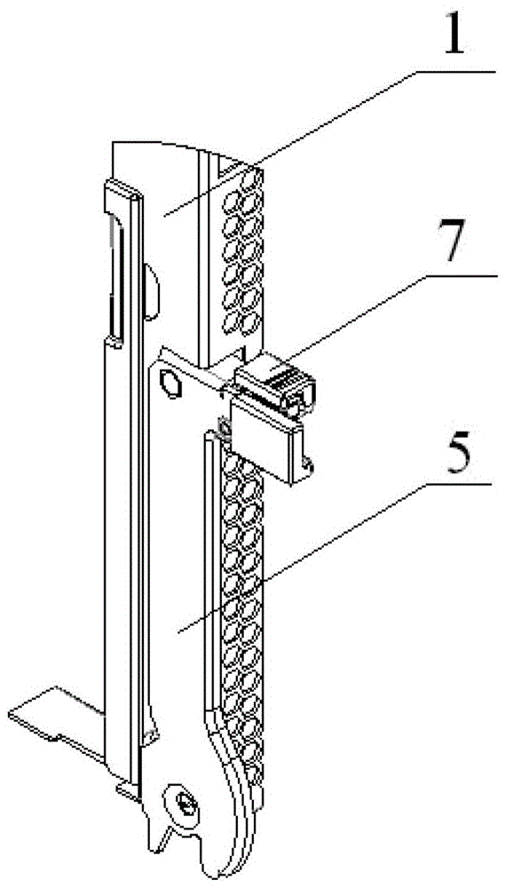
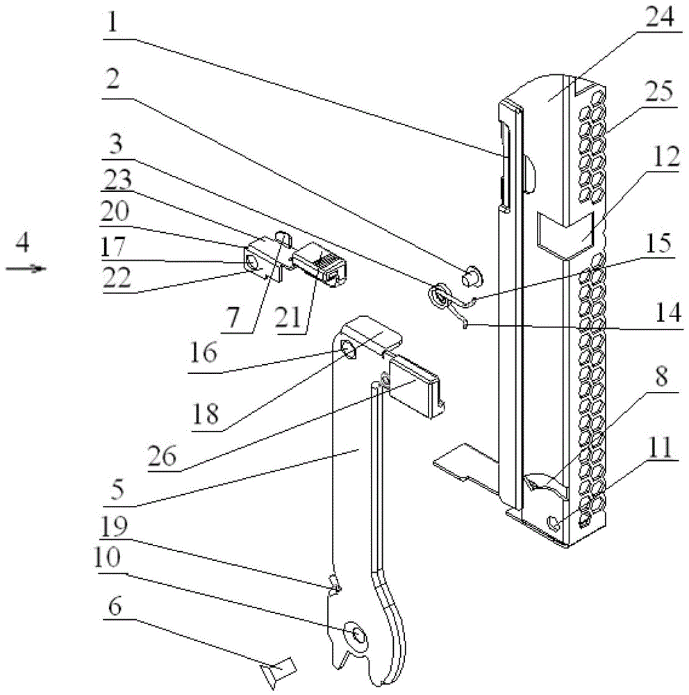
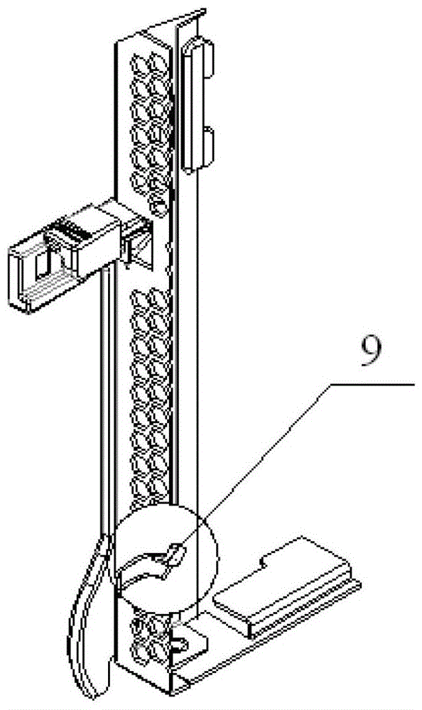
[0018] figure 1 Shown is a support device for a blade according to a specific embodiment of the invention. It includes a housing 1 , an operating handle 5 , and a latch 7 .
[0019] The housing 1 is used to fix the blade in this specific embodiment, so its shape is a cuboid. refer to figure 1 , the operating handle 5 is fixed on the outer surface of the housing 1 , that is, the operating handle 5 and the housing 1 overlap. In the following, the surface of the operating handle 5 in contact with the housing 1 is referred to as "the lower surface of the operating handle 5", and the surface of the operating handle 5 protruding from the housing 1 and parallel to the lower surface of the operating handle 5 is referred to as "the operating handle 5". Since the operating handle 5 is fixed on the outer surface of the casing 1, the same operating handle 5 can be used on casings 1 of various sizes and shapes, which reduces the difficulty and cost of making the operating handle 5.
[...
PUM
 Abstract
Description
Claims
Application Information