

Thermal expansion valve with unidirectional control function
A thermal expansion valve and one-way control technology, applied in the field of thermal expansion valves, can solve problems such as product reliability decline, expansion valve leakage, complex structure, etc., and achieve the effects of simple and reliable installation, convenient structure processing, and lift valve function
- Summary
- Abstract
- Description
- Claims
- Application Information
AI Technical Summary
Problems solved by technology
Method used
Image

Examples
Embodiment 1
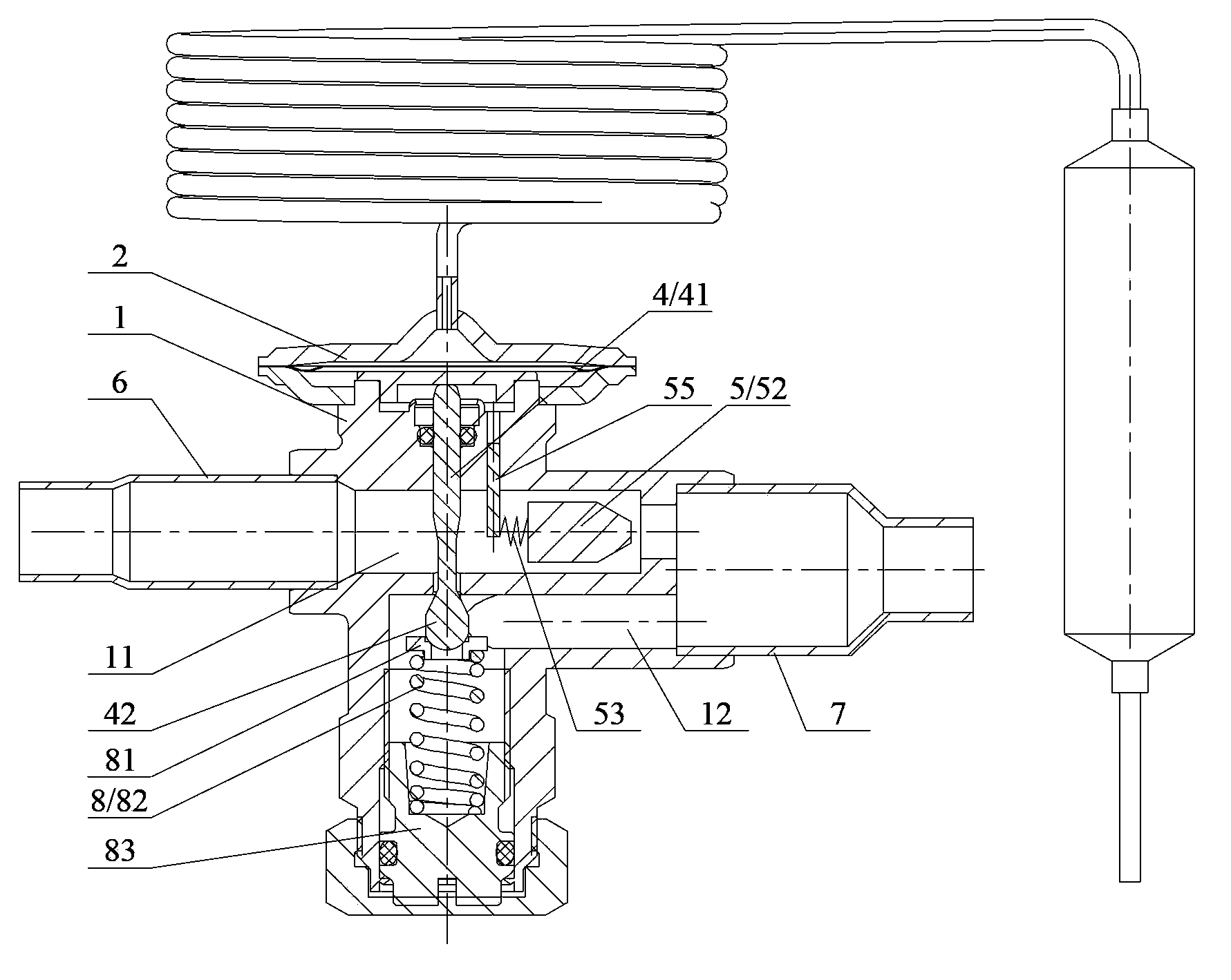
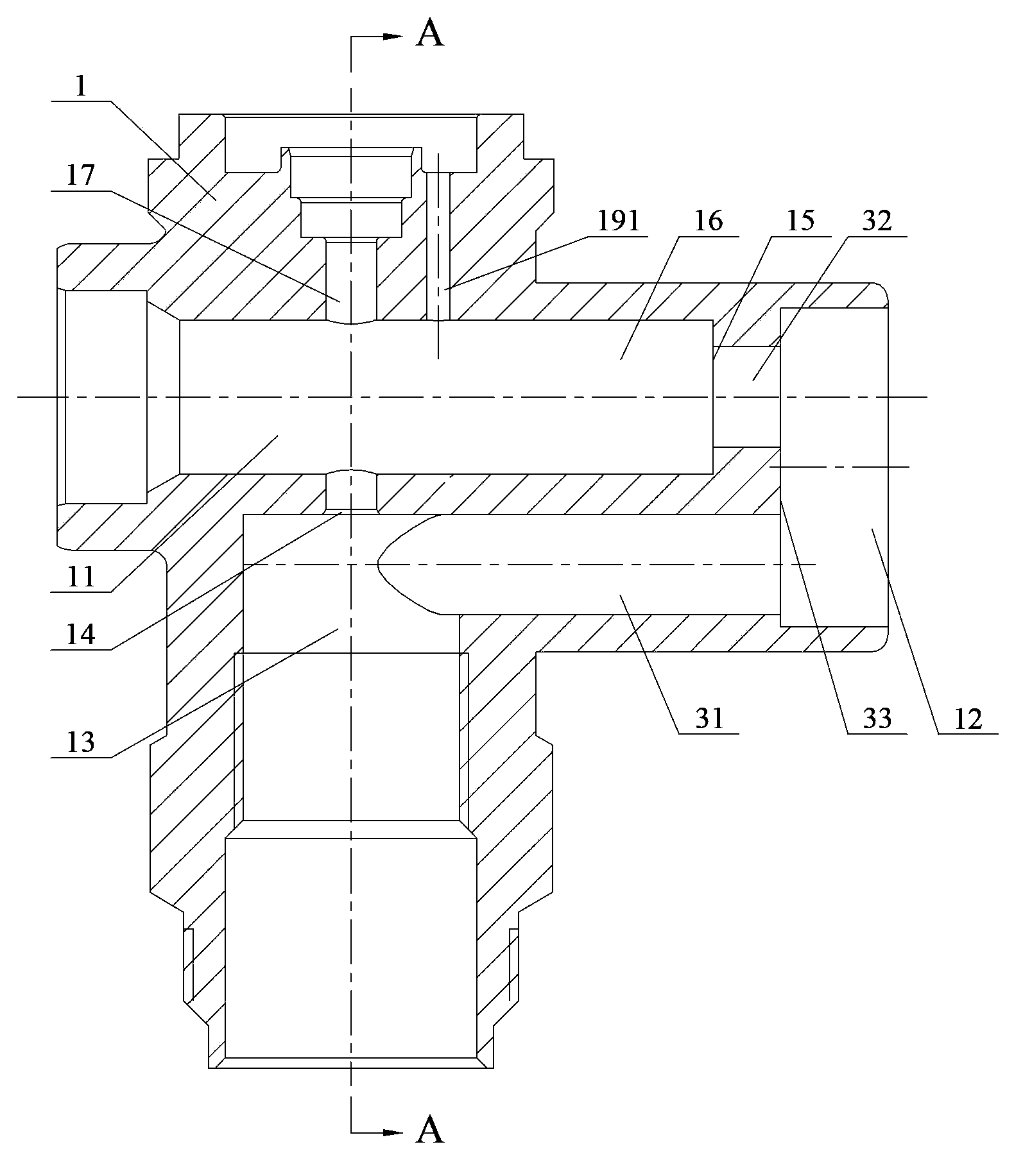
[0029] See figure 2 and image 3 ,in, figure 2 It is a structural schematic diagram of the thermal expansion valve with one-way control function described in the first embodiment, image 3 yes figure 2 Schematic diagram of the valve body structure of the thermal expansion valve described in .
[0030] Such as figure 2 and image 3 shown. In this embodiment, the thermal expansion valve includes a valve body 1, on which an inlet channel 11 and an outlet channel 12 are arranged, and an inner cavity 13 communicating with the inlet channel 11 and the outlet channel 12 is processed in the valve body 1, The temperature sensing component 2 is placed at one end of the valve body 1 . The inner cavity 13 of the valve body 1 also includes a vertical through hole 17 communicating with the temperature sensing component 2 , the lower part of the hole 17 intersects with the inner cavity 13 to form a first valve port 14 .
[0031] The first valve core part 4 is provided through the...
Embodiment 2
[0046] Compared with the first embodiment, this embodiment has the same main body composition and connection relationship. The difference is that in this solution, a further positioning function is added to the inner end of the limit pin rod 55 .
[0047] Please also see Figure 6 and Figure 7 ,in, Figure 6 It is a structural schematic diagram of the thermal expansion valve with one-way control function described in the second embodiment; Figure 7 yes Figure 6 The schematic diagram of the valve body structure of the thermal expansion valve shown in . In order to clearly show the difference between this solution and the first embodiment, components and structures with the same function are marked with the same reference numerals.
[0048] Such as Figure 6 and Figure 7 As shown, opposite to the guide hole 191 in the axial direction, a positioning blind hole 192 is opened on the other side wall of the receiving portion 16 , and the inner end of the limit pin rod 55 i...
PUM
 Abstract
Description
Claims
Application Information