Mooring type fastening assembly

A fastening component and mooring technology, applied in the direction of connecting components, pins, mechanical equipment, etc., can solve the problems of long assembly and disassembly time, large number of tools, inconvenient storage, etc., and achieve simple and easy technical solutions, simple structural processing, The effect of improving work efficiency

Active Publication Date: 2016-04-20
CHINA AVIATION POWER MACHINE INST
View PDF8 Cites 2 Cited by
  • Summary
  • Abstract
  • Description
  • Claims
  • Application Information

AI Technical Summary

Problems solved by technology

[0004] The technical problem to be solved by the present invention is to overcome the problems of many tools, large space, long assembly and disassembly time, many parts are easy to fall, and inconvenient storage when the existing ordinary threaded fastening assembly is assembled and disassembled, and provides a tethered fastening assembly. Tighten the components to improve the integration of the product and avoid the bolts from being independent of the installation components. It is not only easy to use and install, reduces the time of installation / disassembly, improves work efficiency, but also effectively avoids the loss of bolts, washers and other parts, reducing wrong installation, The probability of incidents such as missing installation and foreign objects falling in reduces the space requirements for maintenance

Method used


Image

  • Mooring type fastening assembly
  • Mooring type fastening assembly
  • Mooring type fastening assembly

Examples


Embodiment Construction

[0027] The embodiments of the present invention will be described in detail below with reference to the accompanying drawings, but the present invention can be implemented in many different ways defined and covered by the claims.

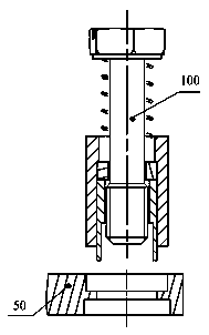
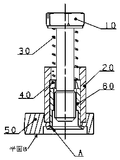
[0028] like figure 2 As shown, the present invention provides a captive fastening assembly, including a captive bolt 100 and a connecting structure 50; specifically, as image 3 As shown, the captive bolt includes an outer sleeve 20, a lock sleeve 60, a spring 30, a half ring 40 and a bolt 10 on the same axis; the outer sleeve 20 and the lock sleeve 60 are cylindrical, and the outer sleeve 20 and the lock sleeve 60 are cylindrical. The inner cavity is divided into two sections, which are respectively the inner cavity of the first outer sleeve and the inner cavity of the second outer sleeve. The inner diameter of the inner cavity of the first outer sleeve is smaller than the inner diameter of the inner cavity of the second outer sleeve; the inner ca...


PUM


Abstract

The invention provides a mooring type fastening assembly. The mooring type fastening assembly comprises a mooring type bolt and a connecting structure. The mooring type bolt comprises an outer sleeve piece, a lock sleeve, a spring, a half ring and a bolt which are arranged on the same axis. The outer sleeve piece and the lock sleeve are cylindrical. An inner cavity of the outer sleeve piece is divided into two segments which are a first outer sleeve piece inner cavity and a second outer sleeve piece inner cavity respectively, and the inner diameter of the first outer sleeve piece inner cavity is smaller than that of the second outer sleeve piece inner cavity. An inner cavity of the lock sleeve is divided into two segments which are a first lock sleeve inner cavity and a second lock sleeve inner cavity respectively, and the inner diameter of the first lock sleeve inner cavity is smaller than that of the second lock sleeve inner cavity. The bolt sequentially comprises a screw head, a screw and a threaded end. The mooring type fastening assembly high in integration degree is provided for overcoming the defects of an existing fastener, the problems that the existing fastener is larger in number of parts and not convenient to use and preserve, and potential safety hazards exist are solved, and a good effect is achieved when the mooring type fastening assembly is applied to an auxiliary power device.

Description

technical field [0001] The present invention relates to the technical field of fasteners, and more specifically, to a captive fastening assembly. Background technique [0002] Fasteners are the most widely used mechanical fastening basic parts, among which threaded fasteners are widely used in various fields. Ordinary threaded fasteners usually include bolts and nuts, which are used in conjunction with the connected parts to Realize the fastening of the connected parts. At present, the commonly used bolt connection structure is shown in the figure below. The bolt passes through the through hole of one or more components and is screwed into the threaded hole of another component; or the bolt passes through two or After the through holes of multiple components, tighten with nuts. When assembling and using, it is necessary to completely pass the rod of the bolt through the bolt hole of the connected part, and then tighten the nut to fasten the connected part; when disassemblin...

Claims


Application Information

Patent Timeline
Patent Type & Authority Applications(China)
IPC IPC(8): F16B13/10
CPCF16B13/04F16B13/10
Inventor 尹星研刘东波史鑫垚李春
Owner CHINA AVIATION POWER MACHINE INST
Why Eureka
Try Eureka