Oil return structure for cooling fan

A cooling fan and oil return tank technology, which is applied to components of pumping devices for elastic fluids, non-variable pumps, machines/engines, etc., can solve the problem of reducing the service life of cooling fans, polluting the internal structure of cooling fans, condensation and other problems, to reduce noise and friction, improve service life, and ensure cleanliness

Active Publication Date: 2016-08-17
DONGGUAN HANSHUO PLASTIC CO LTD
View PDF6 Cites 0 Cited by
  • Summary
  • Abstract
  • Description
  • Claims
  • Application Information

AI Technical Summary

Problems solved by technology

[0005] However, the above-mentioned structure only has one oil return flow channel, and the lubricating grease is a relatively viscous liquid, so its fluidity is not good, resulting in a single oil return flow channel that cannot satisfy all the lubricating grease thrown out. Recycling, there will still be a large part that will be thrown out, that is, the grease return efficiency of the above structure is not good, and the grease thrown out will pollute the internal structure of the cooling fan, and the grease will condense after a long time, so that it hinders The operation of the entire cooling fan reduces the service life of the cooling fan

Method used


Image

  • Oil return structure for cooling fan
  • Oil return structure for cooling fan
  • Oil return structure for cooling fan

Examples


Embodiment Construction

[0031] The present invention will be further described below in conjunction with specific embodiments and accompanying drawings.

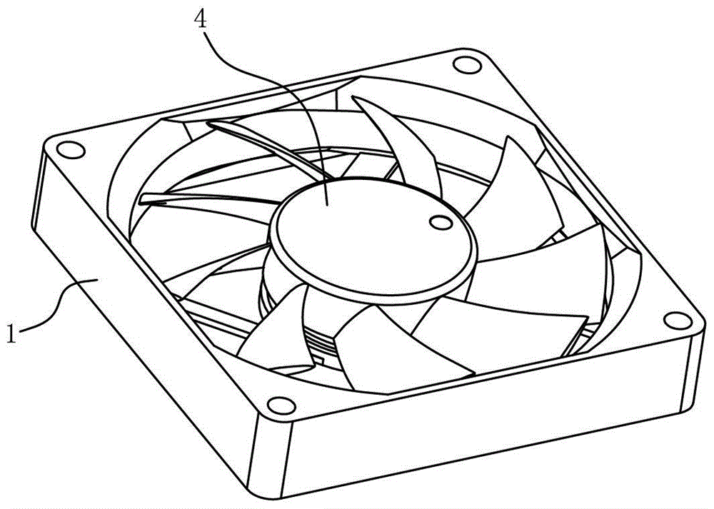
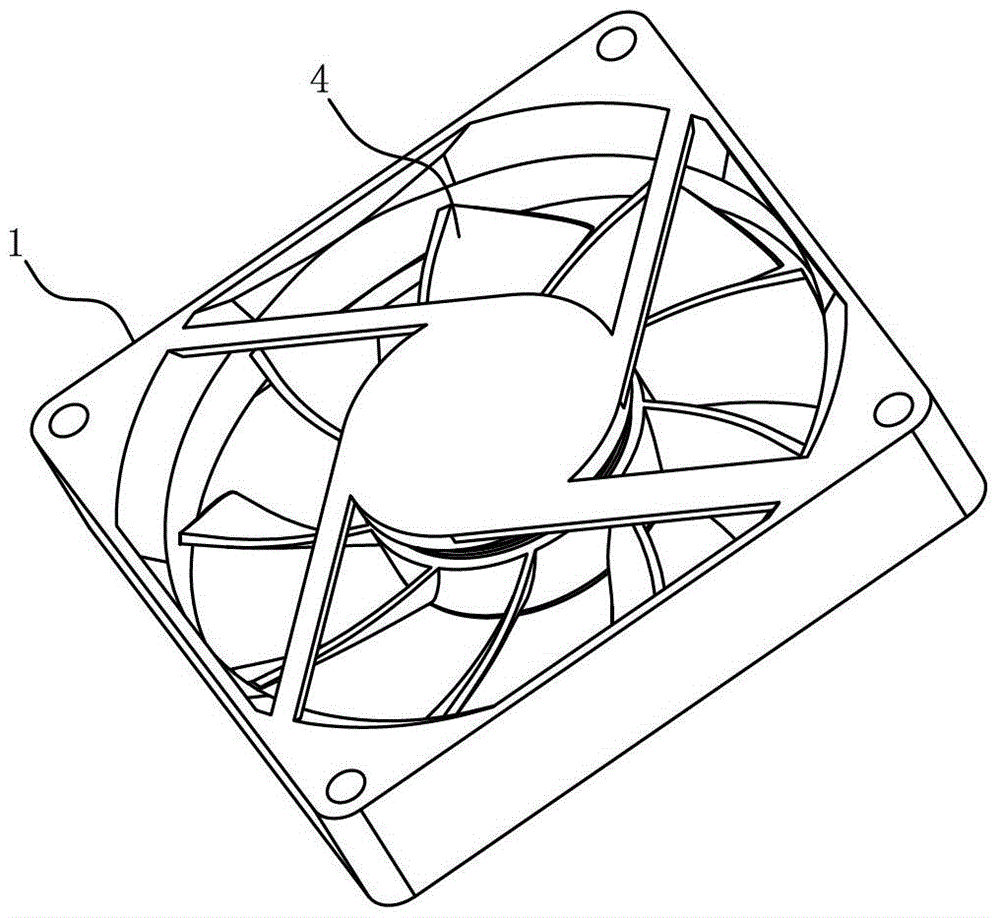
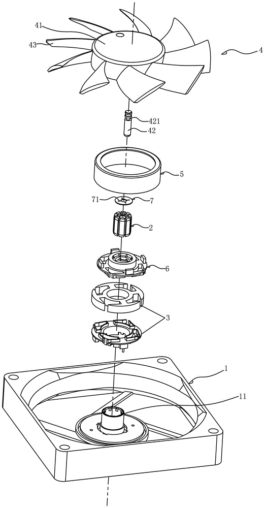
[0032] see Figure 1-11 As shown, an oil return structure for a cooling fan includes: a base frame 1, a bearing 2 mounted on the base frame 1, a stator 3, a fan blade 4, and a rotor 5 matched with the fan blade 4, wherein the rotor 5 is located at The periphery of the stator 3 , wherein the fan blade 4 is arranged on the base frame 1 through a rotating shaft 42 in cooperation with the bearing 2 .

[0033] The middle part of the base frame 1 is formed with an upwardly protruding and hollow center column 11 , and the bearing 2 is installed in the center column 11 . The upper end surface of the central column 11 is provided with several fourth oil return grooves 111, and the bottom of the fourth oil return grooves 111 is an inclined surface, which is convenient for the return of lubricating grease. An oil return frame 6 and an insulating ring piece ...


PUM


Abstract

The invention discloses an oil return structure for a cooling fan. The oil return structure for the cooling fan comprises a base frame, a bearing, a stator, fan blades and a rotor, wherein the bearing, the stator, the fan blades and the rotor are installed on the base frame, an upwards protruding and hollow central pillar is formed in the middle of the base frame, the bearing is installed in the central pillar, a rotation shaft is matched with the bearing so that the fan blades can be arranged on the base frame, an oil return frame and an insulating annular piece are installed on the central pillar of the base frame, a first interval is formed between the central pillar of the base frame and the bearing, a second interval is formed between the bearing and the rotation shaft, the parts, making contact with the fan blades, of the oil return frame, the insulating annular piece and the rotation shaft passing through the first interval and the second interval form a plurality of circulating oil-return flowing passages in a matched and blocking mode, and grease thrown out from the fan blades flows back to the bearing through the oil-return flowing passages. The oil return structure for the cooling fan can basically recycle all the thrown-out lubricating grease through the oil-return flowing passages, enables the lubricating grease to be recycled continuously, is high in backflow efficiency of the lubricating grease, and can effectively reduce noise and frictional force for a long time.

Description

Technical field: [0001] The invention relates to the technical field of computer component products, in particular to an oil return structure for a cooling fan which has high oil return efficiency and can effectively improve the service life of the cooling fan. Background technique: [0002] With the development of the electronic industry, the development of electronic products is gradually evolving towards the direction of high performance, high frequency, high speed and light weight. With the continuous improvement of the performance of electronic products, the calculation speed is getting faster and faster, the calculation speed of the internal chipset is constantly improving, the number of chips is increasing, and the heat emitted by the chips is also increasing correspondingly. If these chips are not dissipated in time Heat will greatly affect the performance of electronic products and reduce the computing speed of electronic products. As the heat continues to accumulat...

Claims


Application Information

Patent Timeline
Patent Type & Authority Patents(China)
IPC IPC(8): F04D29/063
Inventor 谢宏华
Owner DONGGUAN HANSHUO PLASTIC CO LTD
Why Eureka
Try Eureka