Capacitive electrizer

A generator and capacitive technology, applied in the direction of induction generators, etc., can solve problems such as easy interruption of current, obstacles to the convenience of power generation operation, and complex structures

Inactive Publication Date: 2013-11-20
程龙
View PDF5 Cites 3 Cited by
  • Summary
  • Abstract
  • Description
  • Claims
  • Application Information

AI Technical Summary

Problems solved by technology

The disadvantage is that the mobile electrode plate is a discontinuous action, and the current is easily interrupted. At the same time, there are certain obst

Method used


Image

  • Capacitive electrizer

Examples


Embodiment 1

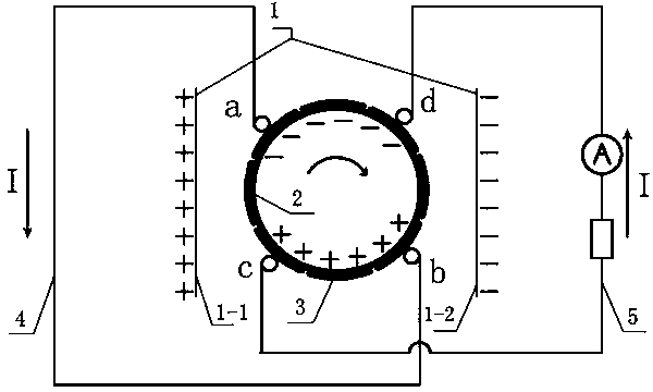
[0021] The present invention will be further described in detail below in conjunction with the drawings, such as figure 1 As shown, the capacitor motor includes: an electrode plate (1), a roller (2) and an external circuit, characterized in that the roller is located between the electrode plates, the roller can roll around the axis of the roller, and the roller There is a non-connected metal sheet (3) on the periphery, and the external circuit is connected with the metal sheet; during the rolling process of the roller, the negative electrons move from a metal sheet with a lower potential to a higher potential connected to it under the action of the electric field force On the metal sheet, the two metal sheets are then separated. Driven by external force, when the metal sheet with negative electrons moves to a lower potential position, at the same time, the metal sheet corresponding to and separated and showing positive electric characteristics When moving to a higher potential ...


PUM


Abstract

The invention relates to a capacitive electrizer which comprises plate electrodes (1), a roller and a periphery circuit. The electrizer is characterized in that the roller is positioned between the plate electrodes, the roller can roll around a roller shaft, the periphery of the roller is equipped with sheet metals (3) which are not connected, and the periphery circuit is connected with the sheet metals. In the rolling process of the roller, negative electrons move from a sheet metal whose electromotive force is relatively low to a connected sheet metal whose electromotive force is relatively high due to effect of electric field force, so that the two sheet metals are separated from each other. Driven by external force, the sheet metal with the negative electrons moves to a position in the lower electromotive force, and when the other sheet metal which is separated from the metal sheet and has positive electricity characteristics moves to a position in the higher electromotive force, the periphery circuit is connected, the live sheet metals discharges, and output is formed.

Description

Technical field [0001] The invention belongs to a power generation device, and particularly relates to a capacitor generator. Background technique [0002] Type a paragraph describing the technical field here. At present, the more commonly used power generation equipment uses electromagnetic induction to convert mechanical energy into electrical energy. The use of large and complex coils causes greater loss and lower efficiency. The output current of this type of power generation equipment is AC. For some DC power equipment, It is troublesome to perform conversion on a specific device. [0003] The capacitive generator published on January 6, 1999, the application number is 97224941.9. The described capacitive generator is to provide an electromotive force and current generated by the change of the electric quantity of the multi-electrode plates by the movement of the electrode plates. The invention has a simple structure and saves materials. The disadvantage is that the moving...

Claims


Application Information

Patent Timeline
IPC IPC(8): H02N1/08
Inventor 不公告发明人
Owner 程龙
Why Eureka
Try Eureka