Switch with arcing chamber

A switch and arc technology, applied in the field of switches with arc extinguishing chamber, to achieve reliable and fast arc extinguishing effect

Inactive Publication Date: 2013-11-20
EATON ELECTRICAL IP
View PDF0 Cites 14 Cited by
  • Summary
  • Abstract
  • Description
  • Claims
  • Application Information

AI Technical Summary

Problems solved by technology

The disadvantage is that the driving force of the magnetic field in the direction of the interrupter only occurs when the current flows in a certain direction

Method used


Image

  • Switch with arcing chamber
  • Switch with arcing chamber
  • Switch with arcing chamber

Examples


Embodiment Construction

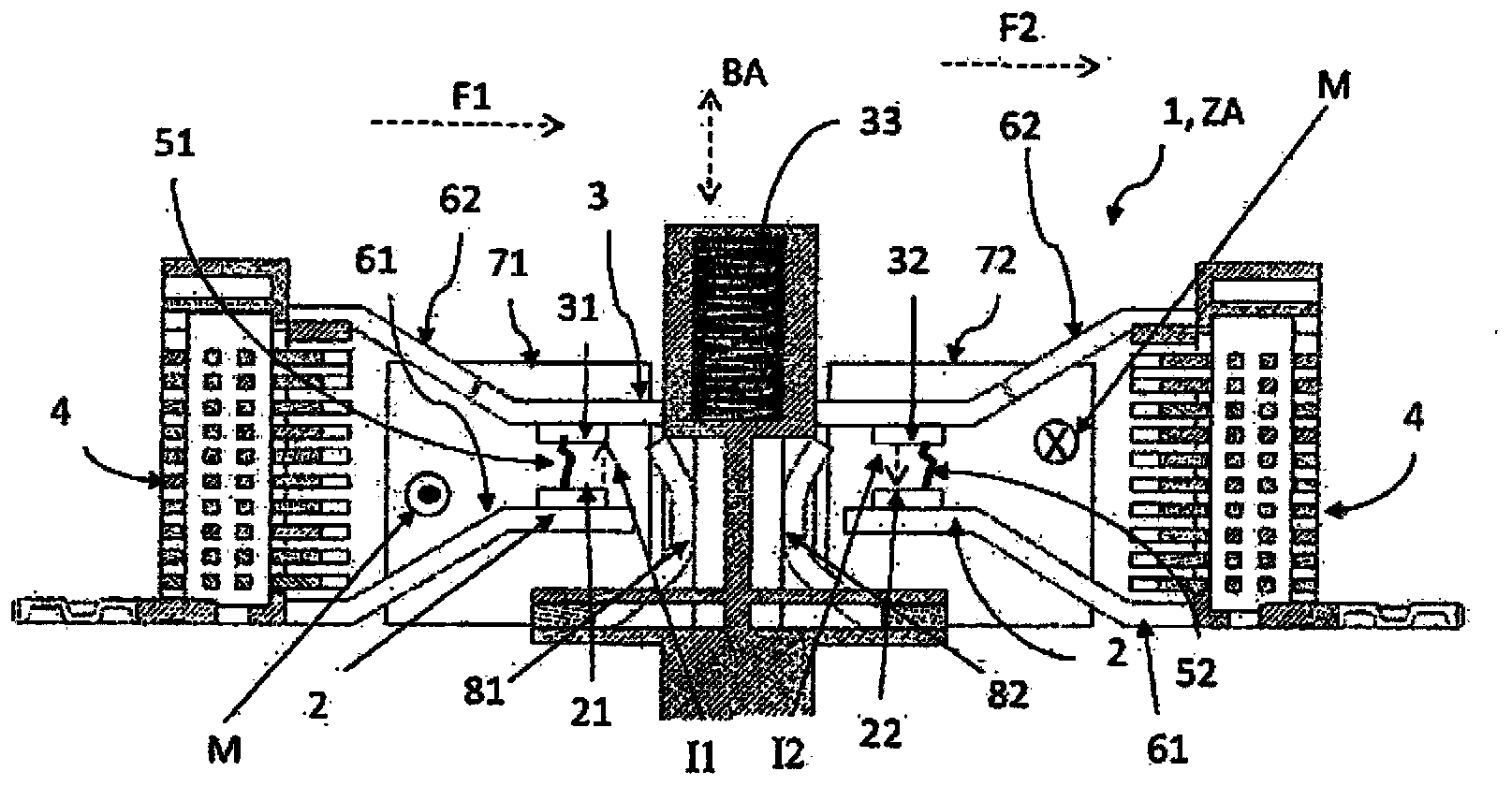
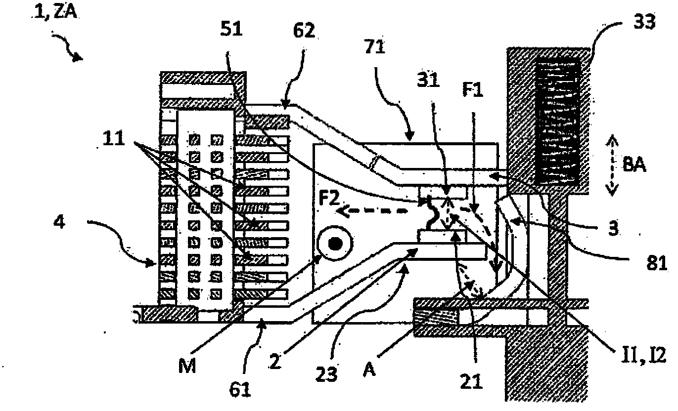
[0025] figure 1 with figure 2 A cross-section of an embodiment of a switch chamber of a switch 1 according to the invention is shown. For the sake of clarity, the drawing is limited to the switch chamber of the switch. It is well known to those skilled in the art that besides the switch chamber, the switch must have other components. Switch 1 is polarity independent due to its construction for DC operation. The entire switch is shown in a symmetrical embodiment in figure 1 in, while figure 2 For better understanding, show figure 1 A magnified view of the left portion of the switch. To this end, the switch 1 comprises: two separate fixed contacts 2 each having a first contact area 21; and a movable conductive bridge contact 3 having second contact areas 31, 32 which The points contact each other along the axis of movement BA of the bridge contact to create an electrically conductive connection between the first contact area 21 , 22 and the second contact area 31 , 32 i...


PUM


Abstract

A fixed contact (2) and conductive movable contact (3) includes contact regions (21,22,31,32). Contact regions of both contacts are electrically connected and separated in ON and OFF states of switch. The magnets (71,72) produces constant magnetic field (M) under contact regions and applies magnetic force (F) in range between contact regions to remove electric arcs (51,52) produced in OFF state along preset direction. Two bridge plates (81,82) remove electric arcs in different direction along movement axis (BA) of movable contact with respect to contact regions of fixed contact.

Description

technical field [0001] The present invention relates to a switch having an arc extinguishing chamber for rapidly extinguishing an arc during the opening process of the switch. Background technique [0002] An electrical switch is a component that creates (switch state "on" or on state) or breaks (switch state "off" or "off" state) an electrically conductive connection in an electrical circuit through internal conductive contacts. When a current carrying connection is to be broken, current flows through the contacts until the contacts separate. If the induction current loop is disconnected by a switch, the current cannot drop directly to 0. In this case, an arc is formed between the contacts. This arc is a gas discharge through a non-conductive medium such as air. Arcs in switches in alternating current (AC) equipment are extinguished at the latest at the zero crossing of the alternating current. Because direct current (DC) has no zero-crossing phenomenon, when the contac...

Claims


Application Information

Patent Timeline
Patent Type & Authority Applications(China)
IPC IPC(8): H01H9/44H01H1/20
CPCH01H9/443H01H1/20H01H9/346H01H33/596H01H33/182
Inventor L·弗里德里克森V·朗
Owner EATON ELECTRICAL IP
Why Eureka
Try Eureka