
Hydraulic driven built-in rotation scraping type pipeline cleaning device

A hydraulically driven and rotary scraping technology, which is applied in the direction of cleaning hollow objects, cleaning methods and tools, chemical instruments and methods, etc., can solve problems such as single structure of pigging devices, limited operating efficiency, and large cleaning resistance of pigs

Active Publication Date: 2013-11-27
钟平贵
View PDF9 Cites 34 Cited by
  • Summary
  • Abstract
  • Description
  • Claims
  • Application Information

AI Technical Summary

Problems solved by technology

[0003] Chinese patent application 200920081193 simple rotary pig, which belongs to a pipeline cleaning tool, solves the problems of high cleaning resistance and high energy consumption in the prior art. The simple rotary pig includes a pig body, cleaning The wheel, the release pipe, and the cleaning plate and guide plate arranged on the pig body. The inside of the pig body is provided with a rotating device and a hollow rotating shaft. The hollow rotating shaft is fixedly connected with the rotating device and passes through the cleaning device. The pipe cleaner body is connected with the discharge pipe and the cleaning wheel set at the front end of the pipe cleaner body
[0006] The existing pigging device has a single structure and does not have versatility. Because the pressure regulation design for fluid passage is not adopted, sometimes the device is stuck in the pipeline due to large particles of dirt and metal scaling on the inner wall of the pipeline, resulting in pressure suffocation. , forming a fluid block, and the operating efficiency is limited. At the same time, due to the lack of positioning structure design, the cleaning equipment cannot complete the complete cleaning of the inner wall of the partial pipeline.
Relevant improved technologies are rarely made public

Method used


Image

  • Hydraulic driven built-in rotation scraping type pipeline cleaning device
  • Hydraulic driven built-in rotation scraping type pipeline cleaning device
  • Hydraulic driven built-in rotation scraping type pipeline cleaning device

Examples


Embodiment Construction

[0026] The present invention will be further described below in conjunction with drawings and embodiments.

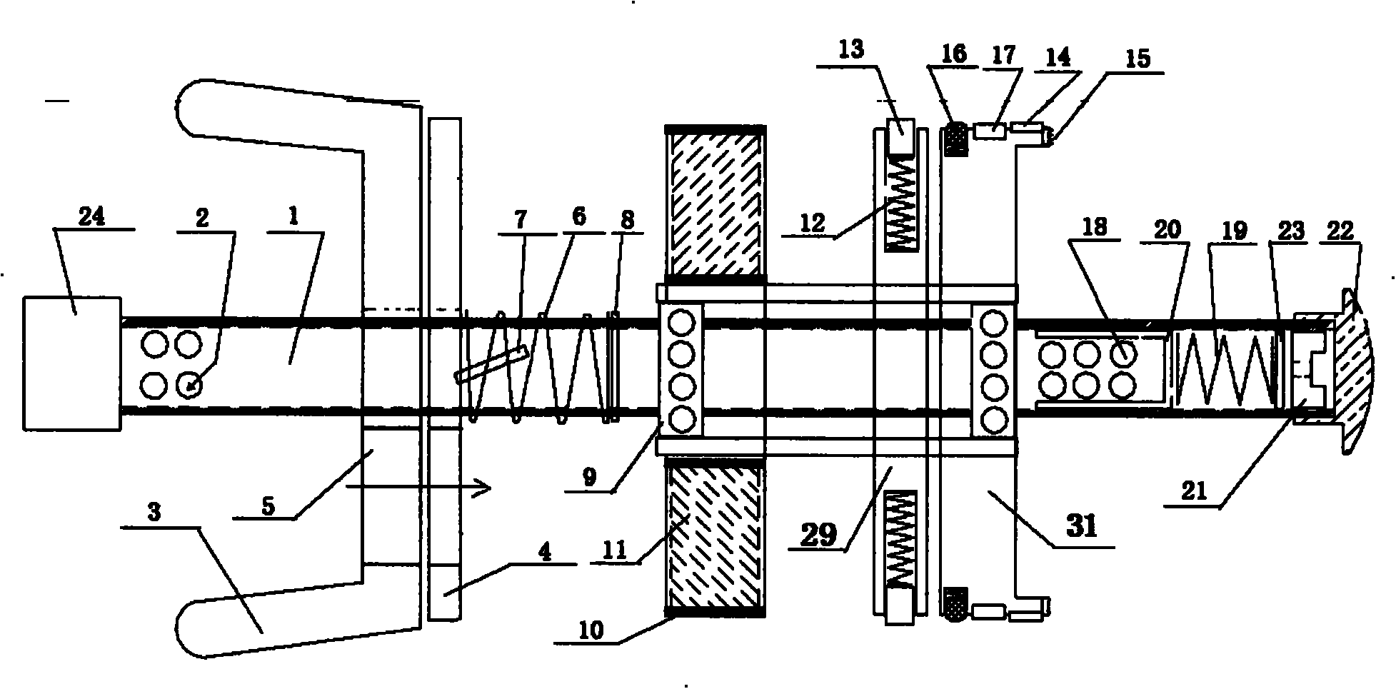
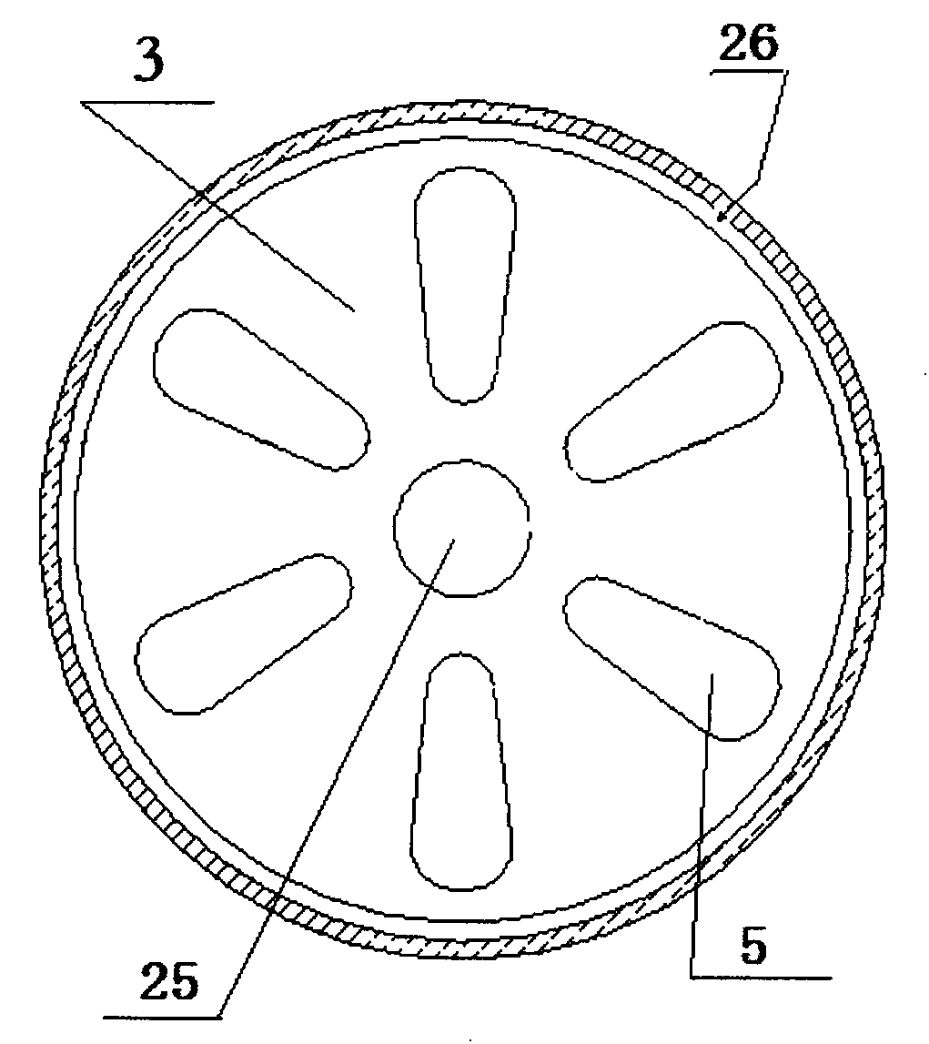
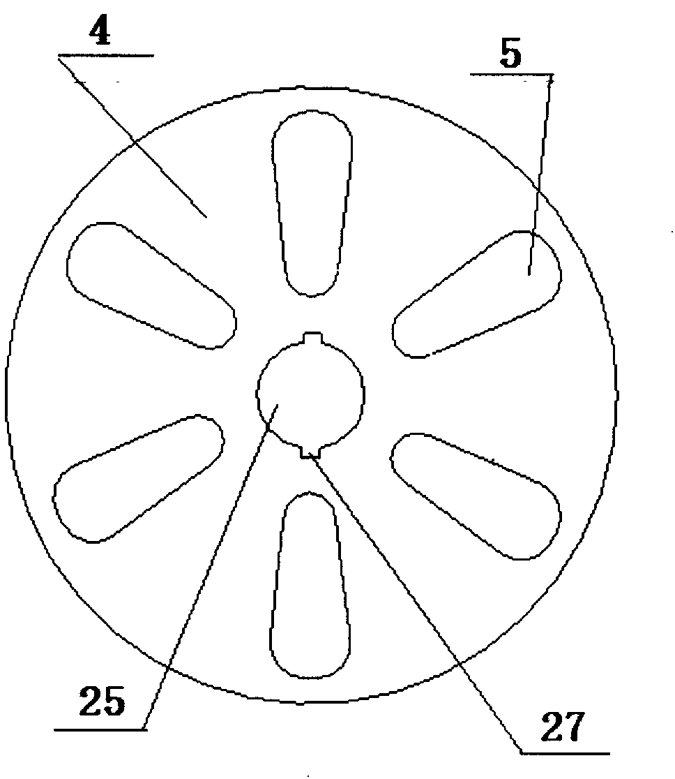
[0027] The present invention includes: main shaft 1, main deflector 3, auxiliary deflector 4, pressure relief hole 5, tapered roller bearing 9, closed impeller 11, fairing 22, blade 28, positioning support frame 29 and composite pigging knife 32.

[0028] as attached figure 1 Shown: the main shaft 1 is connected with the main deflector 3, the auxiliary deflector 4, the tapered roller bearing 9, the closed impeller 11, the positioning support frame 29 and the composite pigging knife 32 sequentially from the back to the front, and the front end of the main shaft 1 is installed Fairing 22, wherein, the main deflector 3 and the auxiliary deflector 4 respectively have a pressure relief hole 5 whose center line is parallel to the axial direction of the main shaft 1, the main deflector 3 is fixedly installed on the main shaft 1, and the auxiliary deflector 4 is slidably insta...


PUM


Abstract

Disclosed is a hydraulic driven built-in rotation scraping type pipeline cleaning device. A main guide plate and an auxiliary guide plate are adopted to form a one-way pressure relief structure, the operating posture of a spindle on the inner central line of a pipeline is maintained through the guide plates, a sealed impeller and a positioning support frame, fluid kinetic energy is used for driving the impeller to drive a pipeline cleaning cutter to clean the pipeline circumferentially in the pipeline, meanwhile, a rim working portion of the composite pipeline cleaning cutter combining effective functions of various pipeline cleaners is further kept in the maximum and optimal contact with the inner wall of the pipeline, the axial portion adopts an alloy grinding head to remove large-particle dirt and metal scaling bonded on the inner wall of the pipeline, the kinetic energy of fluid is used for driving the pipeline cleaning cutter to work, the pipeline can still be in a normal operation state, cleaned dirt can be carried by the fluid quickly and cannot accumulate, and choking of the pipeline can be avoided. The pipeline cleaning device is compact in structure, convenient and flexible, safe and durable, high in popularity, simple to operate, convenient to implement, energy saving, high in cleaning speed, long in cleaning distance and free of damage to the pipeline wall.

Description

technical field [0001] The invention relates to a technology for cleaning or preventing dirt in pipelines of international patent classification B08B, and belongs to an auxiliary device in pipeline maintenance and cleaning construction, in particular to a hydraulically driven built-in rotary scraping pigging device. Background technique [0002] In the prior art, the pig moves in the lumen by its own power or driven by oil and air flow, and is a tool for cleaning the pipe wall and monitoring the internal conditions of the pipe. The pig can carry a radio transmitter and a ground tracking instrument together to form an electronic tracking system. In the pipeline to be operated, put the corresponding series of pigs according to the requirements of the operation. There are generally six series of pigs used in the application of rubber pigs, leather bowl pigs, straight plate pigs, wax scraping pigs, foam pigs, and buckling detectors. The outer edge of the pig cup is elastically...

Claims


Application Information

Patent Timeline
IPC IPC(8): B08B9/057
Inventor 钟平贵
Owner 钟平贵
Learn More