Manipulator conveying device used for automatic detection of commutator

A technology of automatic detection and transmission device, which is applied in the direction of conveyor objects, transportation and packaging, can solve problems such as easy fatigue, and achieve the effect of satisfying transportation and transmission, novel structure and easy control.

Inactive Publication Date: 2013-11-27
三笠电器技研(苏州)有限公司 +2
View PDF8 Cites 15 Cited by
  • Summary
  • Abstract
  • Description
  • Claims
  • Application Information

AI Technical Summary

Problems solved by technology

[0003] After the inspection, take the commutators by hand and place them in the tray one by one. Manual taking wi

Method used


Image

  • Manipulator conveying device used for automatic detection of commutator
  • Manipulator conveying device used for automatic detection of commutator
  • Manipulator conveying device used for automatic detection of commutator

Examples


Embodiment Construction

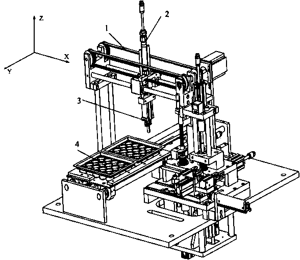
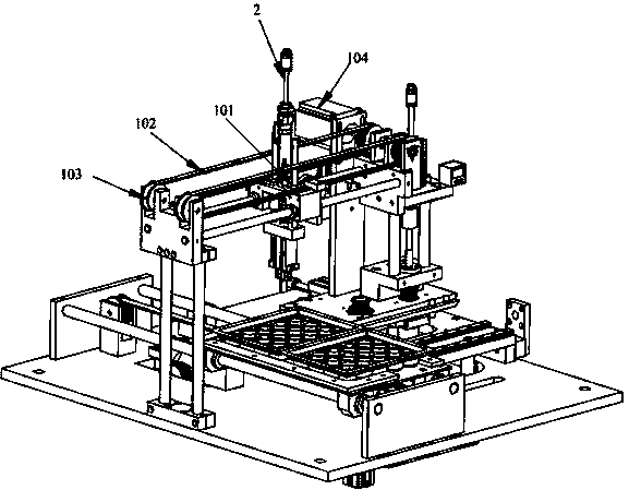
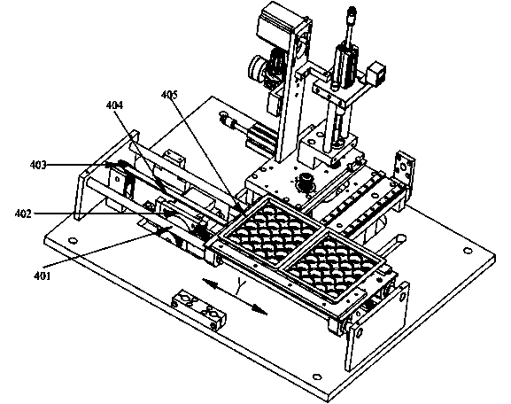
[0017] Such as figure 1 As shown, the manipulator transmission device for automatic detection of commutators includes X-axis transmission unit 1, Y-axis transmission unit 4 and Z-axis transmission unit 2. Y-axis transmission unit 4 includes Y-axis synchronous belt and controls the movement of Y-axis synchronous belt The Y-axis motor, the X-axis transmission unit 1 is located above the Y-axis transmission unit 4, the X-axis transmission unit 1 includes the X-axis synchronous belt and the X-axis motor that controls the movement of the X-axis synchronous belt, and the Z-axis transmission unit 2 is installed on the X-axis transmission On the X-axis timing belt of the unit, the Z-axis transmission unit 2 includes the Z-axis slide rail and the cylinder that controls the movement of the Z-axis slide rail. The clamping hand 3 is installed on the Z-axis slide rail, and the Y-axis transmission unit 4 is on the Y-axis timing belt. A Y-axis motion platform is arranged, and the Y-axis moti...


PUM


Abstract

The invention relates to a manipulator conveying device used for automatic detection of a commutator. The manipulator conveying device comprises an X-axis conveying unit, a Y-axis conveying unit and a Z-axis conveying unit, wherein the Y-axis conveying unit comprises a Y-axis synchronous belt and a Y-axis motor for controlling the Y-axis synchronous belt to move, the X-axis conveying unit is positioned above the Y-axis conveying unit and comprises an X-axis synchronous belt and an X-axis motor for controlling the X-axis synchronous belt to move, the Z-axis conveying unit is installed on the X-axis synchronous belt of the X-axis conveying unit and comprises a Z-axis sliding rail and an air cylinder for controlling the Z-axis sliding rail to move, a clamping paw is installed on the Z-axis sliding rail, a Y-axis motion platform is arranged on the Y-axis synchronous belt of the Y-axis conveying unit, a supporting box is arranged on the Y-axis motion platform, and a three-dimensional motion trace is realized through the coordinative motion and mutual cooperation of the X-axis conveying unit, the Z-axis conveying unit and the Y-axis conveying unit. The manipulator conveying device is easy to control and high in stability.

Description

technical field [0001] The invention relates to a manipulator conveying device, in particular to a manipulator conveying device for automatic detection of a commutator, and belongs to the technical field of automation equipment. Background technique [0002] At present, the flow of the commutator product testing process is: first, the operator manually takes the product to test the high-voltage resistance on a simple high-voltage tester, and then manually takes the product to detect the pressure between the plates in the next process, and then manually takes it The product is tested by the go-no-go gauge, and then the angle of the hook. [0003] After the inspection, take the commutators by hand and place them in the tray one by one. Manual taking will have an impact on the appearance of the product, and workers will be easily fatigued after long-term operation. Contents of the invention [0004] The purpose of the present invention is to overcome the deficiencies in the ...

Claims


Application Information

Patent Timeline
IPC IPC(8): B65G47/90
Inventor 刘健晨胡尧坤
Owner 三笠电器技研(苏州)有限公司
Why Eureka
Try Eureka