A hollow oil pumping device for liquid production profile test

A liquid-producing profile and hollow technology, which is applied in the direction of production fluid, wellbore/well components, earthwork drilling and production, etc., can solve problems such as size limitation of running tools, entanglement of logging cables, and low production of oil wells, so as to prevent reverse flow The effect of sliding and ensuring firmness

Active Publication Date: 2015-12-09
CHINA PETROLEUM & CHEM CORP +1
View PDF7 Cites 0 Cited by
  • Summary
  • Abstract
  • Description
  • Claims
  • Application Information

AI Technical Summary

Problems solved by technology

[0003] At present, the testing techniques of fluid production profile of mechanically pumped wells at home and abroad mainly include: 1. Annulus logging technique, which adopts eccentric wellhead, offsets the production string, and runs the logging instrument through the casing annulus. If the logging cable is entwined with the production string, the logging tool is stuck in the casing annulus, and the size of the running tool is also limited; 2. Double string logging process: two casings are run in the wellbore for production and testing The production string is used for production, and the test instrument is lowered through the test string, which avoids the problem of cable entanglement or instrument jamming. Since two sets of strings are run, there is a higher requirement for the size of the wellbore , only for the upper part is 9 "in cased well
[0004] Due to the low output of oil wells in some oil fields, rod pumps are used for lifting during production, and all use 5 "Completion with small casing, the above two testing processes are difficult to realize due to the limitation of casing size

Method used


Image

  • A hollow oil pumping device for liquid production profile test
  • A hollow oil pumping device for liquid production profile test
  • A hollow oil pumping device for liquid production profile test

Examples


Embodiment Construction

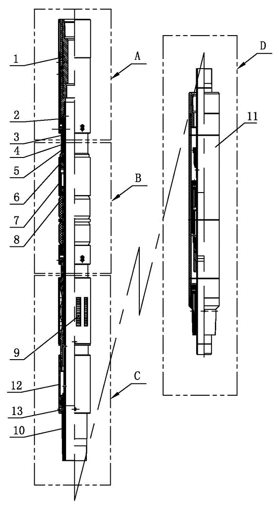
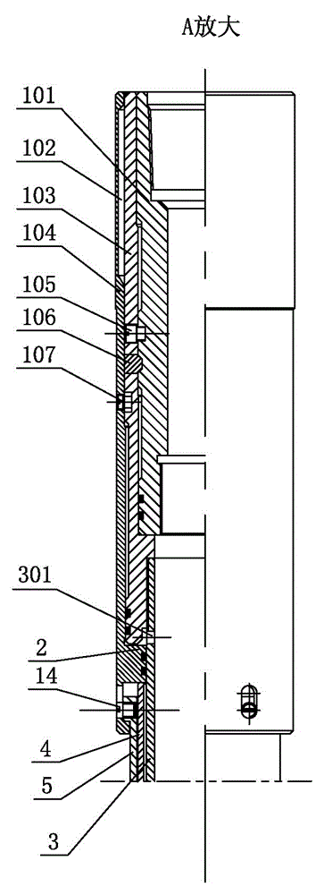
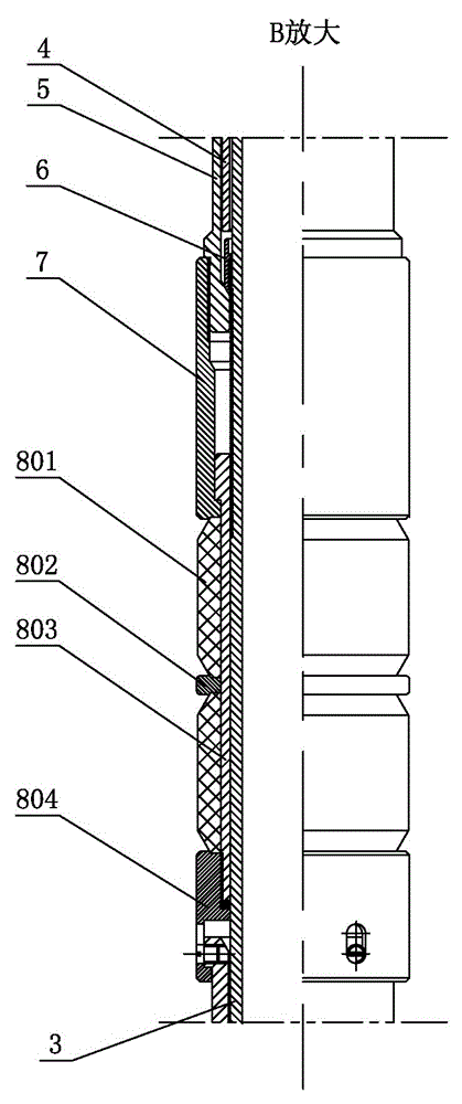
[0019] Such as figure 1 — Image 6 Shown is the hollow oil pumping device for liquid production profile testing of the present invention, including a center tube 3, the upper end of the center tube 3 is threadedly connected to the drop joint 1, the lower end of the center tube 3 is threaded to a lower joint 10, and the lower end of the lower joint 10 is connected with a hollow rod Oil pump 11, the outer wall of the center tube 3 on the lower side of the hand-lost joint 1 slides sequentially with an upper inner ferrule 4 and a lock ring 6, the upper inner ferrule 4 and the lock ring 6 are sheathed with a lock ring sleeve 5, the inner wall of the lock ring 6 and The outer wall of the center tube 3 on the lower side of the lock ring 6 is respectively provided with one-way locking teeth that engage with each other. The outer wall of the lower end of the lock ring sleeve 5 is threadedly connected to the thrust sleeve 7, and the outer periphery of the center tube 3 at the lower end of...


PUM


Abstract

The invention relates to a hollow oil pumping device for fluid producing profile tests in the field of oil field underground oil extraction tools. The hollow oil pumping device comprises a central pipe. A release connector is connected to the upper end of the central pipe in a threaded manner. A lower connector is connected to the lower end of the central pipe in a threaded manner. A hollow rod oil pump is connected to the lower end of the lower connector. An upper inner clamp sleeve and a lock ring are sequentially slidably sleeved on t he outer wall of the central pipe on the lower side of the release connector. A lock ring sleeve is sleeved outside the upper inner clamp sleeve and the lock ring. One-way lock teeth which are meshed are respectively disposed on the inner wall of the lock ring and the outer wall of the central pipe on the lower side of the lock ring. A thrust sleeve is connected to the outer wall of the lower end of the lock ring sleeve in a threaded manner. A packing rubber cylinder and anchoring slips are disposed on the periphery of the central pipe at the lower end of the thrust sleeve. A hydraulic cylinder is disposed on the periphery of the central pipe between the lower end of the release connector and the upper inner clamp sleeve, and a through hole communicated with the inner cavity of the hydraulic cylinder is formed in the wall of the central pipe. By the hollow oil pumping device, oil pumping can be achieved during fluid producing profile tests. In addition, the hollow design provides a passage for instruments and conveying tools to move up and down during the tests.

Description

Technical field [0001] The invention relates to the field of downhole oil extraction tools in oil fields, in particular to a hollow oil pumping device for liquid production profile testing. Background technique [0002] With the production of highly deviated wells and horizontal wells in the oilfield, the water cut gradually rises, and the production efficiency is low and the cost increases in the high water cut period. In order to improve the development effect of this type of well, it is necessary to search for water, determine the water-producing interval of the oil well, and then plug the water. At present, the more accurate method for judging the location of oil well water is to conduct liquid production profile test. Through the liquid production profile test, the oil and water production of the production interval of the oil well can be understood. Based on this, the production adjustment or plugging measures of the oil well can be implemented. Due to the special requirem...

Claims


Application Information

Patent Timeline
Patent Type & Authority Patents(China)
IPC IPC(8): E21B43/00
Inventor 袁玉峰徐贵春唐海军石建设高丽
Owner CHINA PETROLEUM & CHEM CORP
Why Eureka
Try Eureka