
Multi-cylinder inflatable air gun

An inflatable, cylinder technology, applied in the field of firearms, can solve the problems of the limitation of the total elastic force of the inflatable spring, the driving effort, etc., and achieve the effect of adjustable shooting force

Active Publication Date: 2013-11-27
NANPING AUTO FORGING & STAMPING FACTORY
View PDF6 Cites 2 Cited by
  • Summary
  • Abstract
  • Description
  • Claims
  • Application Information

AI Technical Summary

Problems solved by technology

[0003] The invention provides a multi-cylinder self-inflating air cylinder whose elastic force is not limited by the strength of the user and which is labor-saving to drive, which solves the problem that the driving of the existing self-inflating air gun is laborious and the total elastic force of the inflatable spring is limited by the strength of the user. question

Method used


Image

  • Multi-cylinder inflatable air gun
  • Multi-cylinder inflatable air gun
  • Multi-cylinder inflatable air gun

Examples


Embodiment 1

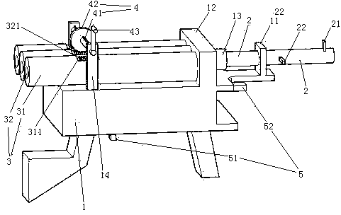
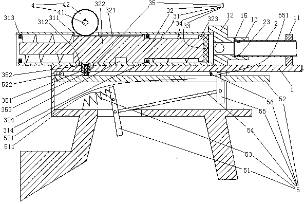
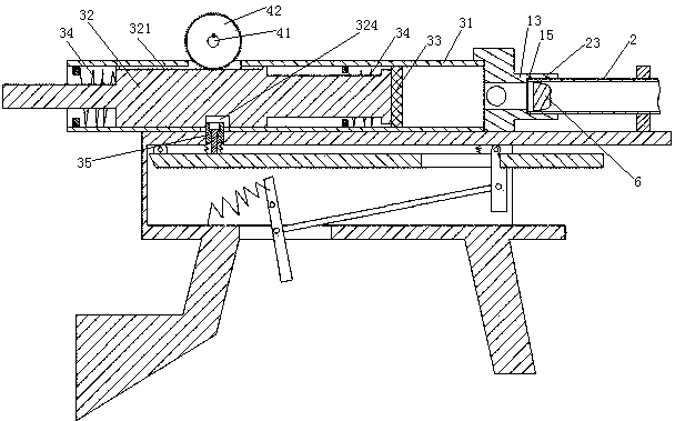
[0024] Embodiment one, see figure 1 , a multi-cylinder self-inflating cylinder, including a gun body 1, a gun barrel 2, a cylinder 3, a piston pulling mechanism 4 and a trigger assembly 5.

[0025] The gun body 1 is provided with a trachea fixing sleeve 11 , an air circuit board 12 and a pair of rotating shaft support blocks 14 . The front end of the air circuit board 12 is provided with an air outlet 13 . A pair of rotating shaft supporting blocks 14 are distributed on the left and right sides of the gun body 1, that is, the front and rear sides in the figure.

[0026] Gun barrel 2 is provided with front sight 21 and handle 22. The handle 22 is positioned at the front of the gun body 1 . The beneficial effect of setting this position of the handle is that the gun barrel will not interfere with the gun body during the process of turning the gun barrel, and the gun barrel can rotate continuously at 360°.

[0027] The gun barrel 2 is set in the trachea fixing sleeve 11 . Th...

Embodiment 2

[0038] Embodiment two, participate in Figure 5 , the difference from the first embodiment is that a pull-out safety pin 7 is provided between the trigger 51 and the gun body 1 . When the safety pin 7 was inserted on the trigger 51, the trigger 51 could not be pulled, so as to prevent accidental shooting.

[0039] Be threaded connection between gun barrel 2 and gun barrel fixing sleeve 11. If the angle of rotation in the first embodiment is small, the number of thread turns connected together between the gun barrel and the gas outlet is less, and when subjected to the impact of high-pressure gas, the connecting threads of the gun barrel and the gas outlet are easily damaged or A bombing accident occurs. In this embodiment, because the screw thread between the gun barrel fixing sleeve and the gun barrel plays the role of auxiliary fixing, it only needs to rotate a smaller angle when the gun barrel is connected and disengaged from the air outlet. The convenience when assembli...

Embodiment 3

[0040] Embodiment three, see Figure 6 , the difference with the second embodiment is that the safety pin 7 is detachably inserted in the locking block mounting plate 52, and the pull rod 351 is connected with the locking block mounting plate 52 through the safety pin 7. When the locking block When 35 is located in the locking groove 324, the locking block 35 and the locking groove abut against each other along the extending direction of the pull rod.

[0041] In this technical scheme, the safety pin not only realizes the safety insurance performance, but also can control the opening number of the cylinder by the safety pin so as to realize the adjustable shooting force and the function of charging multiple shots once.

[0042] The safety pin 7 is provided with a shooting strength mark. There are 4 marks of shooting strength. The four marks of shooting strength are respectively a vacancy mark 711 , a single-cylinder loaded mark 712 , a double-cylinder loaded mark 713 and a t...


PUM


Abstract

The invention relates to firearms, particularly to a multi-cylinder inflatable air gun, which includes a gun body, wherein the gun body is provided with air cylinders, a trigger assembly, a barrel, an air outlet and a piston outward-pulling mechanism, wherein one end of the barrel is detachably sealed and butted with the air outlet; the piston outward-pulling mechanism includes a rotating shaft, and a gear movably connected onto the rotating shaft in the axial direction of the rotating shaft; the at least two air cylinders are arranged side by side in the axial direction of the rotating shaft; each air cylinder includes a cylinder body, a piston, a piston rod, inflating springs for compressing the piston, and a locking block; each piston rod is provided with a locking groove matched with the locking block, and a plurality of teeth matched with the gear and distributed in the axial direction of the piston rod; the locking blocks are movably connected with the trigger assembly; the cylinder bodies are communicated with the air outlet. The multi-cylinder inflatable air gun provided by the invention enables elastic force of the inflating springs to be not limited by force of users, saves labor for driving, and solves the problems that the conventional automatic inflation type air gun consumes much force for driving, and the total elastic force of the inflating springs is limited by force of users.

Description

technical field [0001] The invention relates to firearms, in particular to a multi-cylinder self-inflating cylinder. Background technique [0002] The air gun is a kind of firearm, and its power when shooting comes from the release of high-pressure gas stored in the cylinder or the high-pressure air produced by the instantaneous contraction of the cylinder. In Chinese patent application number is 89216825, and the publication date is August 29, 1990, and the patent document called "short air gun" discloses a kind of self-inflating air gun (self-inflating air gun refers to that the air gun is not inflated by an external inflation mechanism. airsoft gun). Existing self-inflating air guns are inflated in the same way as in this patent document. The user drives all the inflatable springs to store energy at one time, and the air pressure during shooting increases with the increase in the elastic force generated by the inflatable springs. Therefore, the higher the air pressu...

Claims


Application Information

Patent Timeline
Patent Type & Authority Applications(China)
IPC IPC(8): F41B11/62F41B11/70
Inventor 陈学福
Owner NANPING AUTO FORGING & STAMPING FACTORY
Learn More