Metrewave radar angle measurement method

A meter-wave radar and angle measurement technology, which is applied in the radar field, can solve the problems of angle measurement accuracy, detection channel signal processing loss, data signal-to-noise ratio loss, etc., to achieve stable performance, reduce signal-to-noise ratio loss, and angle measurement accuracy high effect

Active Publication Date: 2013-11-27
XIDIAN UNIV
View PDF1 Cites 29 Cited by
  • Summary
  • Abstract
  • Description
  • Claims
  • Application Information

AI Technical Summary

Problems solved by technology

This method has losses due to the signal processing of the detection channel, such as Doppler filtering. When the Doppler filter is not aligned with the Doppler frequency of the target, that is, the Doppler channel is not aligned, resulting in the angle estimation data There is a loss of signal-to-noise ratio, and the accuracy of angle measurement will be affected

Method used


Image

  • Metrewave radar angle measurement method
  • Metrewave radar angle measurement method
  • Metrewave radar angle measurement method

Examples


Embodiment Construction

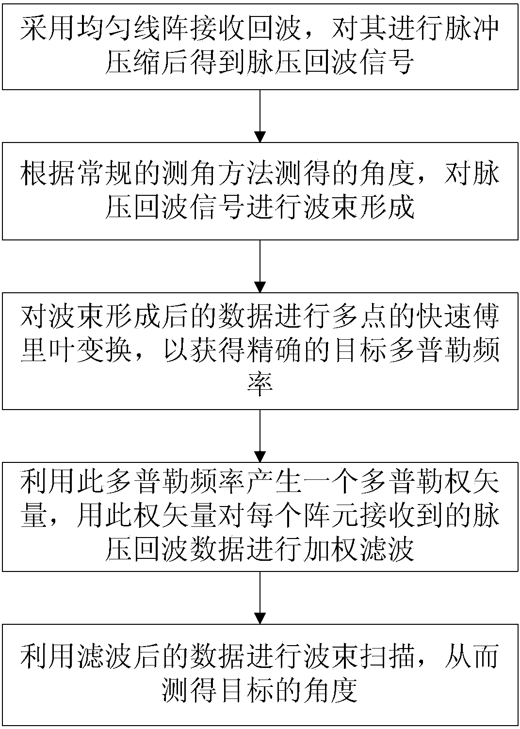
[0028] refer to figure 1 , the specific implementation steps of the present invention are as follows:

[0029] Step 1, using a uniform linear array containing N array elements to receive the meter-wave radar echo signal, and obtaining the pulse pressure echo signal as X after pulse compression, expressed as: X=[x ik ] N×M ,

[0030] where x ik =s T exp(j2πd(i-1)sinθ T / λ)exp(j2πf d (k-1)T r )+w ik Indicates the pulse pressure echo signal of the kth pulse received by the i-th array element, i=1,2,3,...,N, k=1,2,3,...,M, M represents each array element The number of received pulses, s T Represents the initial complex amplitude of the target echo signal after pulse compression, exp represents the exponential power with e as the base, j represents the imaginary number unit, d is the array element spacing, θ T is the angle between the target echo direction and the normal line of the receiving antenna array, λ represents the wavelength of the signal, f d Indicates the Dop...


PUM


Abstract

The invention discloses a metrewave radar angle measurement method which mainly solves the problem that in the prior art, signal to noise ratio loss caused by misalignment of Doppler channels is large. The method comprises the steps of (1) carrying out pulse compression on radar echo signals received by an array to obtain pulse pressure echo signals, (2) estimating the target angle, carrying out beam forming on the pulse pressure echo signals through weight vectors constructed through the target angle, (3) carrying out multi-point fast Fourier transform on data after beam forming to obtain precise Doppler frequencies of a target, (4) generating one Doppler weight vector through the obtained precise Doppler frequencies, carrying out weighted filtering on the pulse pressure echo signals through the Doppler weight vector, and (5) carrying out beam-scanning angle measurement using the data after filtering. The metrewave radar angle measurement method has the advantages of being high in angle measurement precision, and stable in performance, and the method can be used for precise target positioning in the technical field of radars.

Description

technical field [0001] The invention belongs to the field of radar technology, and in particular relates to a method for measuring an angle by a meter-wave radar, which can be used to improve the problem that the accuracy of target angle estimation decreases due to misalignment of Doppler channels in the process of measuring an angle by a meter-wave radar. Background technique [0002] Meter wave radar has unique advantages in over-the-horizon detection and anti-electronic interference, and has been widely valued in recent years. However, due to the long wavelength of the meter wave and the limitation of the size of the antenna, the main lobe beam of the antenna is wide, and the angle measurement accuracy is poor, so it is impossible to accurately locate the target. How to effectively improve the angle measurement accuracy of meter wave radar is still a difficult problem in the radar field. The invention proposes an improved meter wave radar angle measurement method on the ...

Claims


Application Information

Patent Timeline
Patent Type & Authority Applications(China)
IPC IPC(8): G01S13/06
Inventor 赵永波李兵刘宏伟水鹏朗杨金柱朱玉堂
Owner XIDIAN UNIV
Why Eureka
Try Eureka