A matching compression device and matching compression method for linear frequency modulation signal

A technology of linear frequency modulation signal and compression device, which is applied in seismic signal processing, radio wave measurement systems, instruments, etc., can solve the problems of signal-to-noise ratio loss, poor distance resolution, poor image quality, etc., and reduce the loss of signal-to-noise ratio , improve distance resolution, and improve image quality

Active Publication Date: 2015-11-04
BEIJING INST OF RADIO METROLOGY & MEASUREMENT
View PDF1 Cites 0 Cited by
  • Summary
  • Abstract
  • Description
  • Claims
  • Application Information

AI Technical Summary

Problems solved by technology

[0006] In the prior art, pulse compression methods for chirp signals have the following disadvantages: poor distance resolution, loss of signal-to-noise ratio, and poor image quality

Method used


Image

  • A matching compression device and matching compression method for linear frequency modulation signal

Examples


Embodiment Construction

[0043] The content of the invention of the present invention will be further described below in conjunction with the accompanying drawings and embodiments.

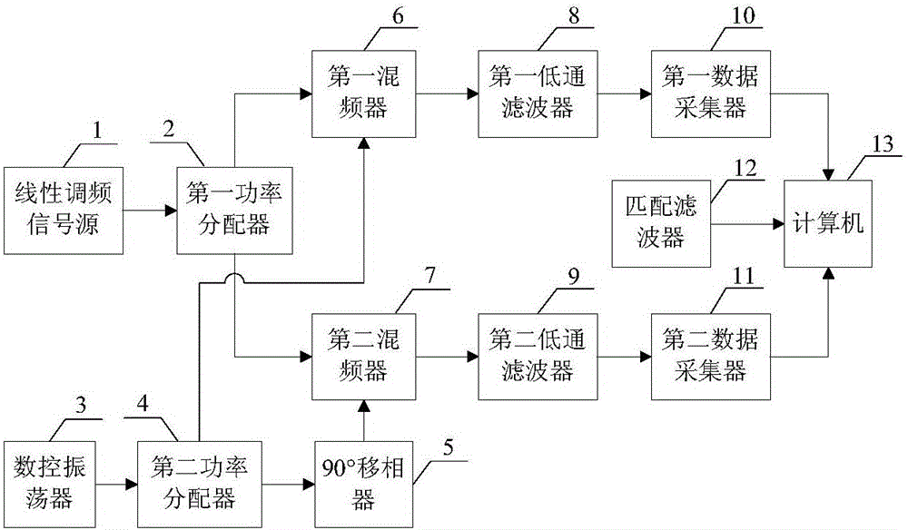
[0044] like figure 1 As shown, the matching compression device for a chirp signal provided in this embodiment includes a chirp signal source 1, a first power divider 2, a numerically controlled oscillator 3, a second power divider 4, a 90° phase shifter 5, First mixer 6, second mixer 7, first low-pass filter 8, second low-pass filter 9, first data collector 10, second data collector 11, matched filter 12 and computer 13.

[0045]The chirp signal source 1 is electrically connected to the first power divider 2 . The first power divider 2 is electrically connected to the first mixer 6 and the second mixer 7, respectively. The numerically controlled oscillator 3 is electrically connected to the second power distributor 4 . The second power divider 4 is electrically connected to the first mixer 6 and the 90° phase shifter ...


PUM


Abstract

The invention discloses a matching compression device for linear frequency modulation signals and a matching compression method. The matching compression device comprises a linear frequency modulation signal source (1), a first power distributor (2), a digital control oscillator (3), a second power distributor (4), a 90-degree phase shifter (5), a first frequency mixer (6), a second frequency mixer (7), a first low-pass filter (8), a second low-pass filter (9), a first data acquirer (10), a second data acquirer (11), a matching filter (12) and a computer (13). Compared with pulse compression devices and compression directions in the prior art, the matching compression device and the matching compression method disclosed in the invention can improve the range resolution, reduce the signal-to-noise-ratio loss, and modify the image quality. The matching compression device and the matching compression method disclosed in the invention can be used for signal processing of radar and earthquake detecting systems.

Description

technical field [0001] The invention relates to the technical field of pulse compression, in particular to a matching compression device and a matching compression method for linear frequency modulation signals. Background technique [0002] With the development of remote sensing technology, the requirements for performance indicators such as radar or fuze range, resolution capability and measurement accuracy are getting higher and higher. If the resolution capability and measurement accuracy of the radar system are to be improved, the radar signal is required to have a large time-width-bandwidth product. However, due to the limitation of the peak power of the transmitting equipment and the feeding equipment of the radar system, the radar signal with higher energy can only be obtained by increasing the pulse width. However, the product of the instant width and the bandwidth of the pulse width of the single-carrier frequency pulse signal is close to 1, so a large pulse width...

Claims


Application Information

Patent Timeline
Patent Type & Authority Patents(China)
IPC IPC(8): G01S7/28G01V1/36
CPCG01S7/285G01V1/36
Inventor 李秀华刘李娟张峰李宏宇高希权李闯
Owner BEIJING INST OF RADIO METROLOGY & MEASUREMENT
Why Eureka
Try Eureka