Close-range detector antenna design method

A design method and detector technology, applied in the direction of design optimization/simulation, special data processing application, radiation element structure, etc., can solve problems affecting antenna beam width, transmission loss, and antenna gain, and achieve small size and high power The effect of large capacity and small volume

Pending Publication Date: 2021-07-02
北京冠群桦成信息技术有限公司
View PDF6 Cites 0 Cited by
  • Summary
  • Abstract
  • Description
  • Claims
  • Application Information

AI Technical Summary

Problems solved by technology

[0007] However, the hood will absorb and reflect the radiated waves of the antenna, which will cause transmission loss, thereby affecting the gain of the antenna, and will also affect the antenna beam width

Method used


Image

  • Close-range detector antenna design method
  • Close-range detector antenna design method
  • Close-range detector antenna design method

Examples


Embodiment 1

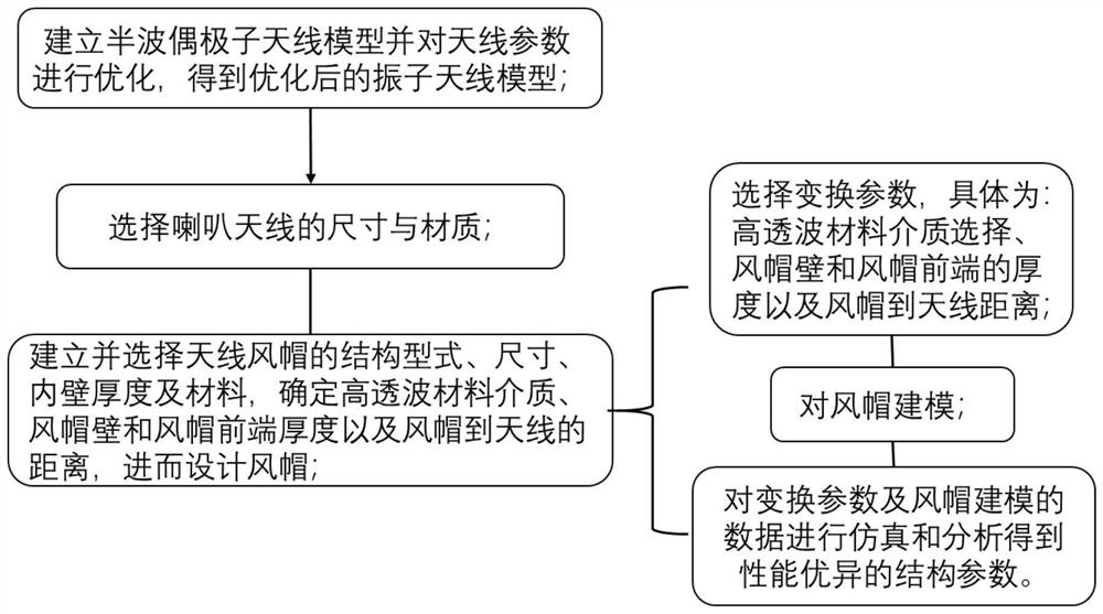
[0043] This embodiment has set forth the principle, core idea and specific implementation process of the antenna design method of a short-distance detector applying the present invention, such as figure 1 shown.

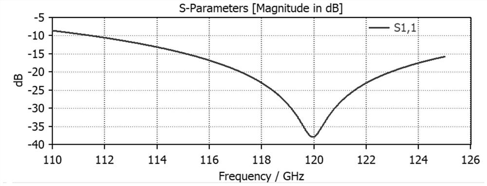
[0044] During the specific implementation of step 1.1, the design operating frequency is a half-wave dipole antenna of 120GHz, and the operating wavelength 2.5mm of the antenna is obtained by the formula λ=c / f, and the two wires forming the antenna are calculated by l=λ / 4, that is, two The length of each half-wave vibrator is 0.625mm; the feed point of the half-wave dipole antenna is at the center of the half-wave dipole antenna, and the impedance of the feed point is pure resistance, approximately 75Ω, and about 73.2Ω during implementation.

[0045] During the specific implementation of step 1.2, since the distance between the wire radius of the half-wave dipole antenna and the endpoints of the two antenna arms is much smaller than the length of the antenna arms, th...


PUM


Abstract

The invention relates to a close-range detector antenna design method, and belongs to the technical field of millimeter wave antennas. Comprising the following steps: 1, establishing a half-wave dipole antenna model and optimizing antenna parameters to obtain an optimized oscillator antenna model; 2, selecting the size and the material of the horn antenna, wherein the horn antenna comprises a horn and an antenna feed source, and the antenna feed source is the 120 GHz half-wave dipole antenna optimized in the step 1, and the loudspeaker adopts a circular waveguide; and 3, establishing and selecting the structural type, the size, the inner wall thickness and the material of an antenna hood, and determining a high-wave-transparent material medium, the thicknesses of the hood wall and the hood front end and the distance from the hood to the antenna so as to design the hood, specifically, 3.A) selecting the high-wave-transparent material medium, the thicknesses of the hood wall and the hood front end and the distance from the hood to the antenna; and 3.B) constructing modeling on the hood. The antenna designed by the method is simple in structure, wide in frequency band, large in power capacity, convenient to adjust and use and very high in resolution and tracking capability, and the anti-interference capability of a detector is greatly improved.

Description

technical field [0001] The invention relates to a design method of a short-distance detector antenna, belonging to the technical field of millimeter-wave antennas. Background technique [0002] The electromagnetic wave with a frequency of 300MHz-300GHz is a microwave frequency band, and the wavelength is between 1mm-1m. The frequency band division of microwave can be divided into decimeter wave, centimeter wave and millimeter wave. Among them, the electromagnetic wave with a frequency range from 30GHz to 300GHz is millimeter wave, which is at the high end of the microwave frequency range. In recent years, millimeter-wave technology has developed rapidly, especially the development of monolithic microwave integrated circuits, which has strongly promoted the wide application of millimeter-wave detectors. The advantage of millimeter wave is that it is easy to achieve a narrow beam width with a short wavelength, it has high resolution and tracking ability in detecting objects, ...

Claims


Application Information

Patent Timeline
Patent Type & Authority Applications(China)
IPC IPC(8): G06F30/20H01Q1/36
CPCG06F30/20H01Q1/36
Inventor 秦俊峰姚云燕沈光张前悦杨宗富胡亚超
Owner 北京冠群桦成信息技术有限公司
Why Eureka
Try Eureka