
A kind of LED lamp ballasted by bidirectional thyristor

A technology of LED lamps and LED lamp boards, which is applied in the direction of lamp circuit layout, lighting devices, light sources, etc., can solve the problems of lifespan not as good as LED lamps, drive circuits need to be strengthened, etc., and achieve no radio frequency interference, low operating current, and low cost Effect

Inactive Publication Date: 2016-10-05
林士干
View PDF5 Cites 0 Cited by
  • Summary
  • Abstract
  • Description
  • Claims
  • Application Information

AI Technical Summary

Problems solved by technology

Because the drive circuit of the traditional LED tube or light bulb uses electrolytic capacitors and active components, although the efficiency and output current are stable, the life of the existing LED drive circuit is far less than that of the LED lamp. Often the LED lamp has not been damaged, and the drive circuit has premature death
In order to prolong the life of the LED lamp, the life of the drive circuit needs to be strengthened

Method used


Image

  • A kind of LED lamp ballasted by bidirectional thyristor
  • A kind of LED lamp ballasted by bidirectional thyristor

Examples


no. 1 example

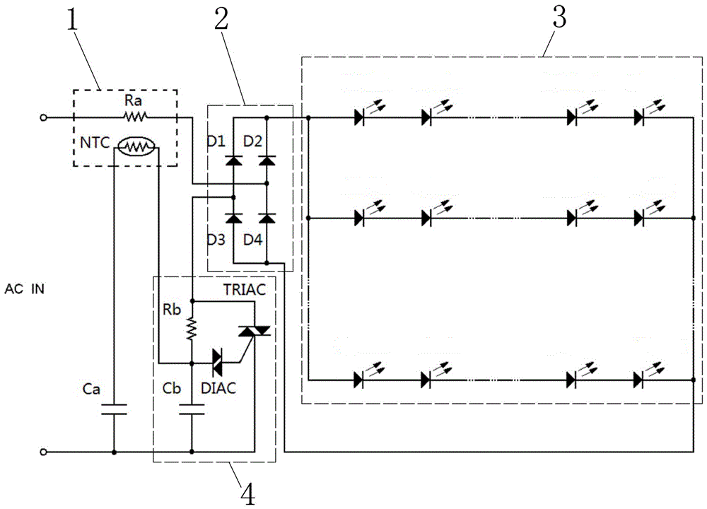
[0014] The first embodiment, such as figure 1 As shown, an LED lamp ballasted by a bidirectional thyristor, including a thermal induction unit 1, a power adjustment unit 4, a bridge rectifier 2 and a DC LED lamp board 3, a thermal induction unit 1, a bridge rectifier 2, and a DC LED The lamp boards 3 are connected in series, and the power adjustment unit 4 is connected to the power supply and the bridge rectifier 2 . Among them, the thermal sensing unit 1 is formed by coupling the negative temperature coefficient thermistor NTC and the current limiting resistance Ra, and the power adjustment unit 4 is formed by connecting the non-polar capacitor Cb, the resistor Rb, the bidirectional trigger diode DIAC and the bidirectional thyristor TRIAC , the bridge rectifier 2 is formed by connecting diodes D1, D2, D3, and D4, and the DC LED lamp panel 3 is composed of a number of light-emitting diode groups connected in series and then connected in parallel. Its circuit connection relati...

no. 2 example

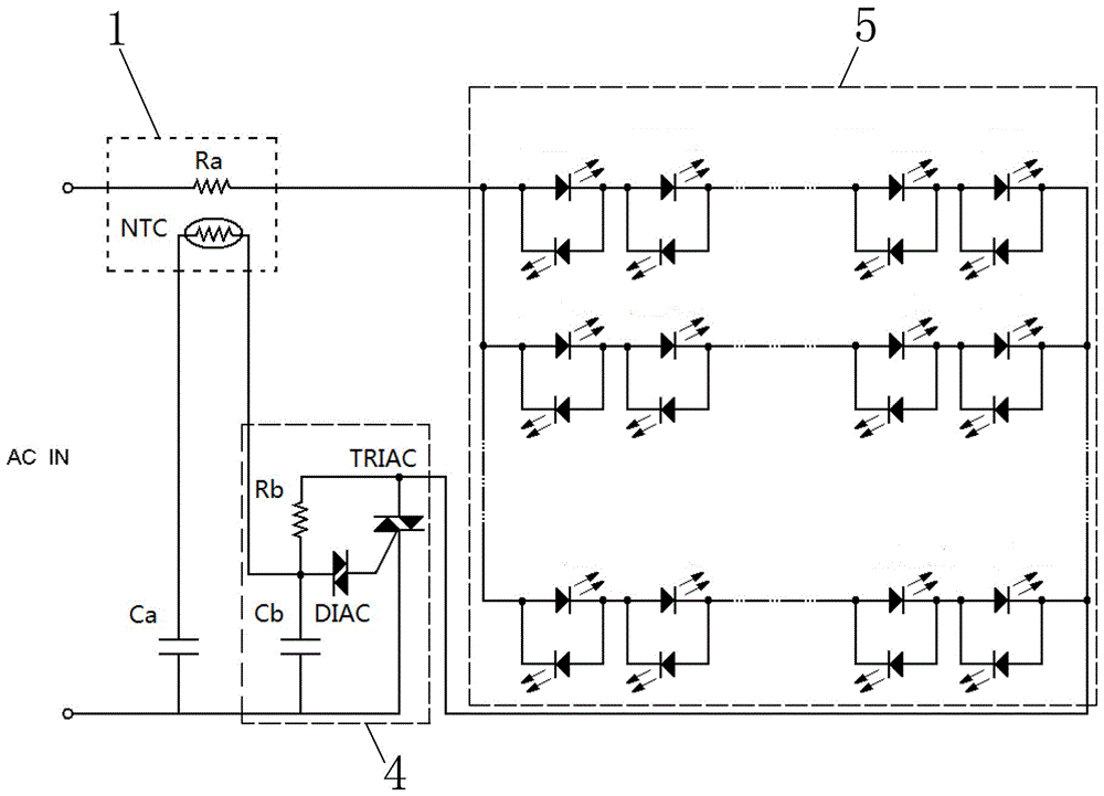
[0015] Second embodiment, such as figure 2 As shown, an LED lamp ballasted by a bidirectional thyristor includes a thermal induction unit 1, a power adjustment unit 4 and an AC LED lamp board 5, the thermal induction unit 1 is connected in series with the AC LED lamp board 5, and the power adjustment unit 4 connect power supply. Among them, the thermal sensing unit 1 is formed by coupling the negative temperature coefficient thermistor NTC and the current limiting resistance Ra, and the power adjustment unit 4 is formed by connecting the non-polar capacitor Cb, the resistor Rb, the bidirectional trigger diode DIAC and the bidirectional thyristor TRIAC , the AC LED lamp panel 5 is composed of several groups of two light-emitting diodes connected in parallel and then connected in parallel again. One end of the power supply, the non-polar capacitor Ca is connected in series with the negative temperature coefficient thermistor NTC, and the non-polar capacitor Ca and the two ends...


PUM


Abstract

The invention discloses an LED lamp achieving ballasting through a bi-directional thyristor. The LED lamp comprises a thermal induction unit, a power adjusting unit, a direct-current LED lamp panel and a bridge rectifier. The thermal induction unit is sequentially and electrically connected with the bridge rectifier and the direct-current LED lamp panel, and the power adjusting unit is electrically connected with a power supply and the bridge rectifier. The thermal induction unit comprises a thermo-sensitive resistor and a current-limiting resistor, wherein the thermo-sensitive resistor and the current-limiting resistor are coupled. By means of the thermo-sensitive resistor and the current-limiting resistor, the amount of heat, generated due to changes of currents in the electrifying process, of the current-limiting resistor influences the amount of impedance of the thermo-sensitive resistor, and accordingly the amount of the impedance of the thermo-sensitive resistor influences the power adjusting unit in a circuit, so that power of the circuit is adjusted. Besides, the effect of adjusting the brightness of the LED lamp or the ballasting effect is achieved.

Description

technical field [0001] The invention relates to the field of LED lamps, in particular to an LED lamp ballasted by bidirectional thyristors. Background technique [0002] Lamps made of LEDs have the advantages of low power consumption, low heat generation, and long service life, and have been widely used in various fields. Because the drive circuit of the traditional LED tube or light bulb uses electrolytic capacitors and active components, although the efficiency and output current are stable, the life of the existing LED drive circuit is far less than that of the LED lamp. Often the LED lamp has not been damaged, and the drive circuit has Die early. In order to prolong the life of the LED lamp, the life of the driving circuit needs to be strengthened. Contents of the invention [0003] The technical problem to be solved by the present invention is to provide an LED lamp ballasted by bidirectional thyristors that can match the lifespan of LEDs against the above-mentioned...

Claims


Application Information

Patent Timeline
Patent Type & Authority Patents(China)
IPC IPC(8): H05B37/02
Inventor 林士乾
Owner 林士干
Learn More