
Detachable type dry powder material gasifying tool

A gasification bed and dismantling technology, which is applied in the field of dismountable dry powder material gasification bed, can solve the problems of easy formation of cement plug, low linear velocity, difficulty in cement gasification input pipeline, etc., and achieve uniform and stable gas flow and gasification. The effect of increasing the area and preventing recoil into the gas supply manifold

Inactive Publication Date: 2013-12-04
山东胜油固井工程技术有限公司
View PDF6 Cites 0 Cited by
  • Summary
  • Abstract
  • Description
  • Claims
  • Application Information

AI Technical Summary

Problems solved by technology

[0003] In the past, the gasification technology mostly used nozzle gasification technology. From the distribution and angle of the nozzle position, the formed fixed rotating gasification flow is close to the central part of the tank, and the linear velocity is lower than the sedimentation velocity of cement, which is easy to form a cement plug
The cement plug becomes very dense and strong under the action of low external air pressure, which makes it very difficult for the cement gasification input pipeline

Method used


Image

  • Detachable type dry powder material gasifying tool
  • Detachable type dry powder material gasifying tool
  • Detachable type dry powder material gasifying tool

Examples


Embodiment Construction

[0019] In order to further disclose the technical solutions of the present invention, the following will be described in detail through examples in conjunction with the accompanying drawings:

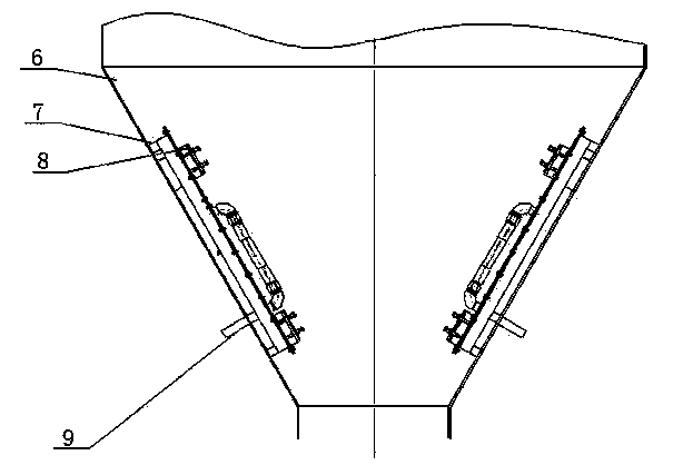
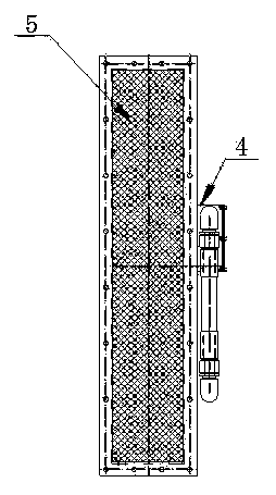
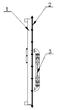
[0020] The present invention includes a gasification bed base 1, a gasification layer 5, a gasification layer pressure plate 2, an air inlet pipe 3 and a gas distribution chamber 4, and is characterized in that the gasification bed base 1 is set as a rectangular groove, and a bolt with a bolt is arranged on the edge of the slot. The connection plate 8 of the hole is provided with a gasification layer 5 covering the notch on the connection plate 8, and a gasification layer pressing plate 2 with bolt holes is provided on the side of the gasification layer 5, and the connection with the gasification bed seat 1 Corresponding to the plates 8, they are connected together with bolts; a rectangular gas distribution chamber 4 with a sealing cover is provided in the middle of one side of the gasif...


PUM


Abstract

A detachable type dry powder material gasifying tool comprises a gasifying tool base, a gasifying layer face, a gasifying layer face pressing plate, a gas inlet pipe and a gas flow dividing chamber. The detachable type dry powder material gasifying tool is characterized in that the gasifying tool base is arranged to be a rectangular groove, a connecting plate with a bolt hole is arranged on a groove opening edge, the connecting plate is provided with the gasifying layer face which covers a groove opening, the gasifying layer face pressing plate with the bolt hole is arranged on the side of the gasifying layer face and corresponds to the connecting plate on the gasifying tool base, the gasifying layer face pressing plate and the connecting plate are connected together through a bolt, a rectangular gas flow dividing chamber with a sealing cover is arranged in the middle of one side of the gasifying tool, a flow dividing plate with small evenly-densely-distributed holes is arranged on a communicating hole of the gasifying tool base and the bottom of the gas flow dividing chamber, a gas inlet pipe is arranged on the upper side face of the gas flow dividing chamber, the gas inlet pipe, a stand type cone-shaped lower dust tank gas inlet and an air compressor are connected, the bottom of the gasifying tool base is arranged on the side wall of a cone-shaped lower dust tank in an attaching mode, and the gasifying tool is fixed on the side wall of the cone-shaped lower dust tank through the connecting plate arranged on the side wall of the cone-shaped lower dust tank and the fixing bolt which fixes the gasifying layer face.

Description

technical field [0001] The invention relates to a detachable dry powder material gasification bed of a vertical lower ash tank. Background technique [0002] The vertical lower ash tank is widely used in the cementing operation of oil and gas wells, and it is also widely used in the construction of key projects such as national defense, construction, mines, ports, and power stations. The transportation of bulk cement can make the cement fluidized. However, how to create good fluidization conditions, that is, the "gasification" state, is the key technology that determines the reliability and economy of the entire "gasification delivery system". [0003] In the past, the gasification technology mostly used nozzle gasification technology. From the distribution and angle of the nozzle position, the formed fixed rotating gasification flow is close to the central part of the tank, and the linear velocity is lower than the sedimentation velocity of cement, which is easy to ...

Claims


Application Information

Patent Timeline
IPC IPC(8): B01F13/02B01F33/40
Inventor 王小华王崇德焦永强胡潍孙月燕
Owner 山东胜油固井工程技术有限公司
Learn More