Wing for an aircraft, aircraft and method for reducing aerodynamic drag and improving maximum lift

An aircraft, high-lift device technology, applied in the direction of affecting air flow, drag reduction, aircraft parts, etc. flowing through the surface of the aircraft

Active Publication Date: 2013-12-04
AIRBUS OPERATIONS GMBH
View PDF6 Cites 12 Cited by
  • Summary
  • Abstract
  • Description
  • Claims
  • Application Information

AI Technical Summary

Problems solved by technology

however, it is questionable whether this measure can completely eliminate stalls in a certain flight envelope bandwidth
However, it can be assumed that this measure prevents the local stall region from extending further to the outside to a considerable extent

Method used


Image

  • Wing for an aircraft, aircraft and method for reducing aerodynamic drag and improving maximum lift
  • Wing for an aircraft, aircraft and method for reducing aerodynamic drag and improving maximum lift
  • Wing for an aircraft, aircraft and method for reducing aerodynamic drag and improving maximum lift

Examples


Embodiment Construction

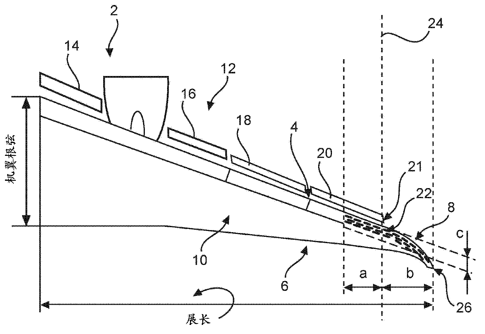
[0033] The outboard slat 20 is positioned adjacent to the wingtip extension 8 such that, after deployment, the end face 21 of the outboard slat 20 is in an upstream position affecting the airflow around or impinging on the wingtip extension 8 . Furthermore, due to the significant increase in the angle of attack of the wing 2 during take-off or landing phases, the flow characteristics over the unprotected wingtip extension 8 may be inhomogeneous and produce stall and flow separation phenomena, respectively.

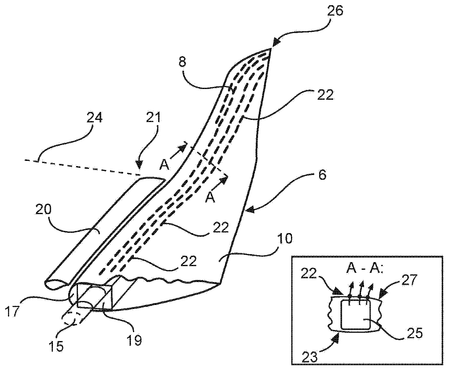
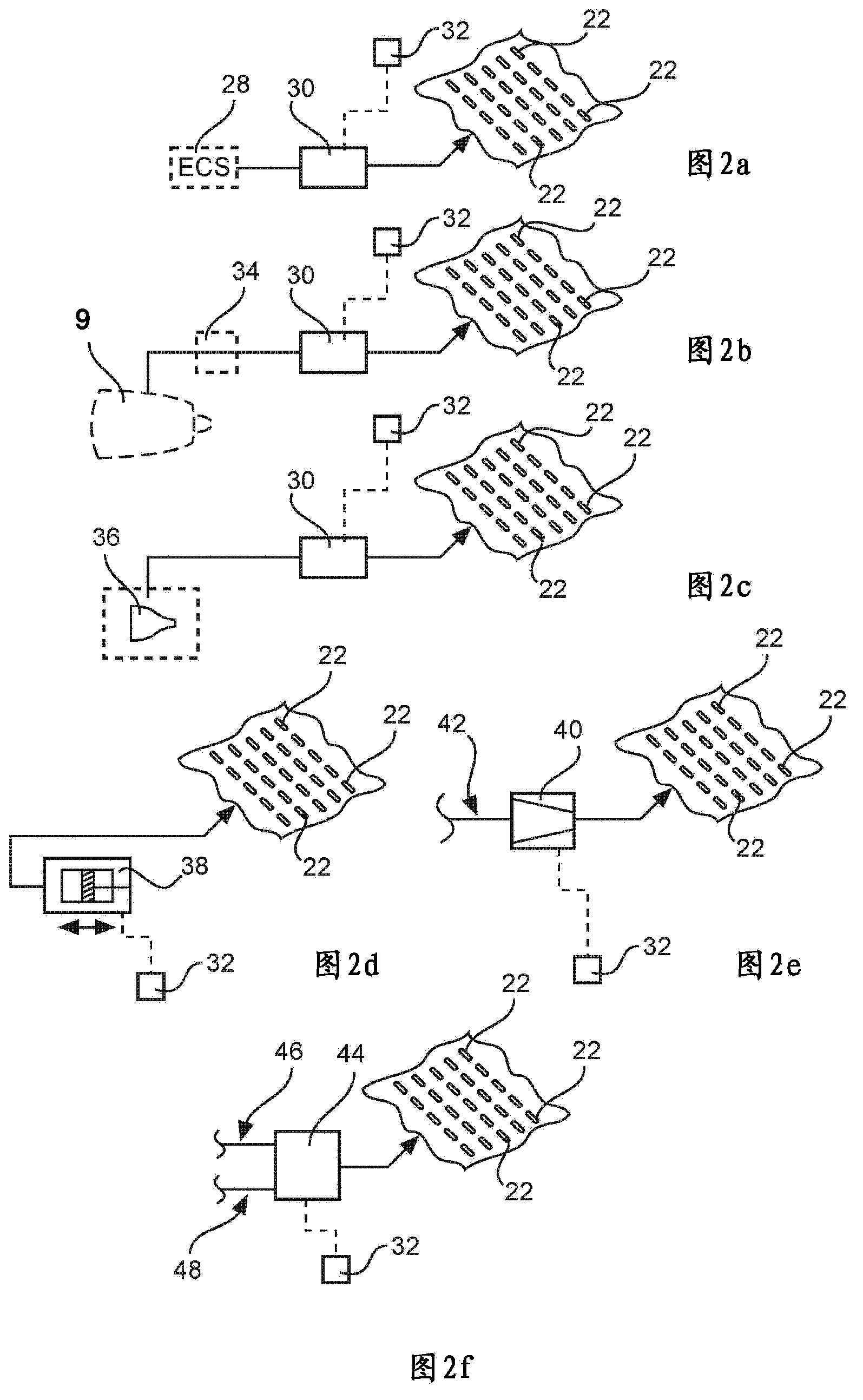
[0034] In order to harmonize the local flow over the wingtip extension 8 and substantially avoid flow separation over the wingtip extension 8 , on the wingtip extension 8 and in regions located more inwardly adjacent to the wingtip extension 8 An arrangement of openings 22 is provided. These openings 22 are the central part of the local flow control device for influencing the local flow by sucking in air or blowing out air.

[0035] In order to increase aerodynamic lift a...


PUM


Abstract

A wing (2) for an aircraft comprises a leading edge (4) and a wing tip extension (8) extending from an end of a main wing region to a wing tip (26). The wing tip extension (8) comprises an arrangement of openings (22) at least from the end of a main wing region to the wing tip (26) along the leading edge (8), which openings (22) are connected to an air conveying device for conveying air through the openings (22).Thereby in flight states with a low flight velocity the flow around a wing tip extension can be harmonized such that the drag is decreased and the lift of the wing is increased. The invention further relates to a method for reducing the aerodynamic drag and improving the maximum lift, and an aircraft.

Description

[0001] Cross References to Related Applications [0002] This application claims priority to European Patent Application No. 12162156.9, filed March 29, 2012, and U.S. Provisional Patent Application No. 61 / 617,169, filed March 29, 2012, the entire contents of which applications are incorporated by reference into this article. technical field [0003] The invention relates to a wing for an aircraft, an aircraft and a method for reducing aerodynamic drag and increasing maximum lift. Background technique [0004] In commercial aircraft, wingtip extensions are often installed to improve efficiency, since lift-induced drag can be reduced and lift generated at the wingtips can be increased. Since wingtip extensions are generally designed for cruising flight conditions, they may exhibit undesired stall behavior during takeoff and landing. Although the airfoil itself usually includes high-lift devices, for example in the form of slats placed on the leading edge, the purpose of whi...

Claims


Application Information

Patent Timeline
Patent Type & Authority Applications(China)
IPC IPC(8): B64C21/02
CPCY02T50/162B64C23/065Y02T50/164Y02T50/166B64C21/02B64C23/069Y02T50/10
Inventor 丹尼尔·雷克策布尔哈德·格尔林马西亚斯·伦格斯
Owner AIRBUS OPERATIONS GMBH
Why Eureka
Try Eureka