Eureka AIR delivers breakthrough ideas for toughest innovation challenges, trusted by R&D personnel around the world.

Vertical lifting aerodyne employing tiltable ducted wheels

A technology of helicopters and ducts, applied in the field of helicopters, can solve the problems of affecting traffic order, wing restrictions, etc., and achieve the effects of light structure, small aerodynamic resistance, and large internal volume.

Inactive Publication Date: 2015-08-26
NANJING UNIV OF AERONAUTICS & ASTRONAUTICS
View PDF4 Cites 13 Cited by
  • Summary
  • Abstract
  • Description
  • Claims
  • Application Information

AI Technical Summary

Problems solved by technology

However, for several mainstream flying cars in the world (such as X-Hawk, Hoverbike, Airphibian), the power drive for driving on the ground and the lift system in the flight stage are independent. The wing is a large-sized autorotor. When driving or taking off and landing on the road, it not only affects the normal traffic order, but also is restricted by roadside obstacles.

Method used


Image

  • Vertical lifting aerodyne employing tiltable ducted wheels
  • Vertical lifting aerodyne employing tiltable ducted wheels
  • Vertical lifting aerodyne employing tiltable ducted wheels

Examples


Embodiment Construction

[0030] The present invention provides a helicopter using tiltable ducted wheels, in order to make the purpose of the present invention, the technical scheme and effect more clear and clear, and the present invention will be further described in detail with reference to the accompanying drawings and examples. It should be understood that the specific implementations described herein are only used to explain the present invention, but not to limit the present invention.

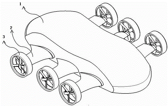
[0031] The present invention provides a helicopter using tiltable ducted wheels, and its overall structure schematic diagram is as follows: figure 1 As shown, it includes a body 1, a side wing 2 and a ducted wheel 3. The end of the side wing 2 is connected to the ducted wheel 2 through a tilting system, and the tilting system is connected to the end of the side wing 2 by plugging and plugging. There are gears on the outer surfaces of the two ends of the duct, and the tilting system is rotated through the gear t...


PUM


Abstract

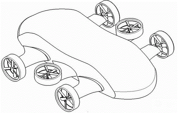
The invention relates to a vertical lifting aerodyne employing tiltable ducted wheels. A fuselage adopts the streamline design, two sides of the fuselage are provided with large strake wing body-fused horizontal fixed stub wings, tilting systems are designed at the tail ends of the stub wings and connected with the earth-space dual purpose ducted wheels, the ducted wheels are overturned towards the inner side of the fuselage through the tilting systems, and thus the vertical lifting aerodyne can run on the ground, take off and land vertically and fly in the air with any attitude. Six stub wings are designed at both sides of the fuselage in total, so that six ducted wheels are required in total. The vertical lifting aerodyne has the advantages that the technology of fusing the streamline fuselage and wing bodies is adopted, and thus the structure weight is light, the internal capacity is large, the air resistance is small; control over the flight attitudes is realized through controlling power differentials of the six wheels, the design of control rules is simple, and the control is convenient.

Description

technical field [0001] The invention belongs to a driving tool for both ground and air, in particular to a helicopter using tiltable ducted wheels. Background technique [0002] Since the advent of the first flying car in 1917, people have begun to explore a lot of flying cars. Over the years, inventors and flying enthusiasts have designed a variety of flying cars with good performance. Today's traffic congestion is becoming more and more serious, and countries are racing to develop flying cars. Research in this field is becoming more and more important. At present, hundreds of flying car patents have been obtained around the world, and a variety of flying prototypes have been developed. The prototype has been put into small batch production. The development of flying cars has become a general trend. However, for several mainstream flying cars in the world (such as X-Hawk, Hoverbike, Airphibian), the ground driving power drive and the lift system in the flight phase are in...

Claims


Application Information

Patent Timeline
Patent Type & Authority Applications(China)
IPC IPC(8): B60F5/02B64C27/52
Inventor 黄道博高闪邹茂真李沂霏
Owner NANJING UNIV OF AERONAUTICS & ASTRONAUTICS
Why Eureka
Eureka Blog
Learn More