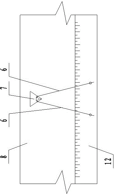
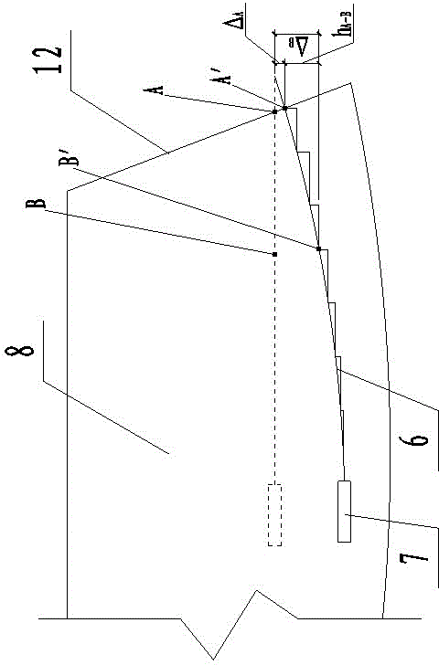
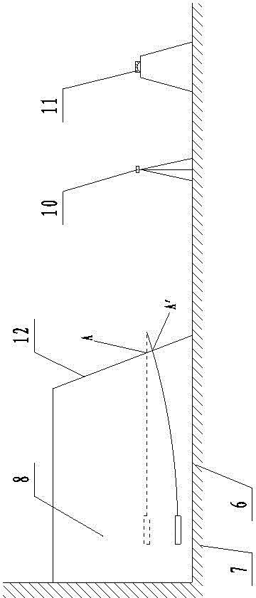
[0037] The present invention uses an inclinometer to measure settlement deformation through an angle-adjustable converter. The inclinometer 9 installed on the measuring rope 4 moves in the settlement tube 6 through the angle-adjustable converter 7 to measure the high filling of the single air surface. Settlement deformation of square foundation 8;
[0038] like Figure 4 As shown, the structure of the angle adjustable converter 7 is as follows: including a triangular prism frame 1, a multi-angle adjustable pulley block 2, a joint pipe 3 and a cover plate, the multi-angle adjustable pulley block 2 is installed inside the triangular prism frame 1, and the triangular prism A side edge of the frame 1 is provided with a guide adjustment groove column 5, and the bottom of the multi-angle adjustable pulley block 2 is set in the guide adjustment groove column 5, and the guide adjustment groove column 5 is provided with a plurality of adjustment holes and is connected with the positioning screw. The multi-angle adjustable pulley block 2 is fastened and fixed. On the triangular prism frame 1, a joint pipe 3 is respectively hinged on the two rectangular side frames corresponding to the side edges provided with the guide adjustment groove column 5. The triangular prism frame The outer surface of 1 is equipped with a cover plate and the two side frames on which the joint pipe 3 is installed leave a rotation gap for the joint pipe 3 to rotate. The structure of the multi-angle adjustable pulley block 2 is: a vertical bar of a T-shaped bar Set in the guide adjustment groove column 5, the two ends of the cross bar of the T-shaped bar are respectively hinged with one end of a connecting rod, and a pulley is installed at the other end of each connecting rod;
[0039] The measurement method includes the following steps:
[0040] The first step is to select the datum point and observation section, such as image 3 As shown, set a reference point in a stable section, and select a representative observation section as the embedding position of the settlement tube 6 and the angle-adjustable converter 7 according to the actual requirements of the site project and the terrain conditions, forming a V-shaped measurement line;
[0041] In the second step, the settling tube 6 and the angle-adjustable converter 7 are buried, such as figure 1As shown, on the observation section selected in the first step, two settling pipes 6 are laid according to the included angle required by the project, and the settling pipes 6 protrude from the observation section by 0.5-1m, and the angle can be adjusted according to the included angle in the converter 7. The positions of the two pulleys and the rotation angles of the two joint pipes 3, and the adjusted angle-adjustable converter 7 is placed at the junction of the two settling pipes 6, and each settling pipe 6 communicates with a joint pipe 3 respectively , a measuring rope 4 is placed in the two settling tubes 6 and the measuring rope 4 passes through the two joint pipes 3 and two pulleys in the angle-adjustable converter 7, and the two ends of the measuring rope 4 pass through the two settling tubes respectively 6 stretch out the observation section;
[0042] The 3rd step, observe and record the initial data, set an observation point every interval of 0.5m or 1m in the settling tube 6, measure the elevation and the embedding direction of the section outlet points of the two settling tubes 6 with reference to the datum point with the elevation measuring instrument 10 and Record,
[0043] The fourth step is to measure the elevation of the exit point of the cross section after settlement. After filling a layer of soil on the high fill foundation and settling for a period of time, use the elevation measuring instrument 10 to observe the cross section exit point of the two settlement pipes 6 after the settlement of the reference point. the elevation and record it;
[0044] In the fifth step, the inclinometer is zeroed, and the inclinometer 9 is connected to the measuring rope 4 in one of the settlement tubes 6. The cable of the inclinometer 9 is connected to the indicator, and the inclinometer 9 is connected to the settling tube 6. Calibrate and zero at the nozzle;
[0045] The sixth step, settlement deformation measurement, pulls one end of the measuring rope 4 that is not installed with the inclinometer 9, drives the inclinometer 9 in the other settlement tube 6 to move, and reads the reflected data of the inclinometer 9 at each observation point, and record it;
[0046] The seventh step is data collation and analysis.
[0047] In the sixth step, after the inclinometer 9 moves in a settling tube 6 and the measurement is finished, the inclinometer 9 is placed in another settling tube and the fifth and sixth steps are repeated to measure and record, realizing a Simultaneous measurement of the V-shaped line of the observation section, low cost, easy to use, time-saving and labor-saving.
[0048] In the sixth step described in the observation point measurement, pull the measuring rope 4 to drive the inclinometer 9 to measure multiple observation points back and forth in a settling tube 6, and record the reflection data of each observation point, so that each observation point The measurement data is more accurate.
[0049] Before zeroing the inclinometer in the fifth step, align the probe guide wheel with the vertical guide groove and place it in the corresponding settling tube 6 for 3-5 minutes to balance the probe with the underground temperature and ensure measurement accuracy .
[0050] In the second step, when the settling pipes 6 are buried, they are connected one by one, and each settling pipe is inserted into half of the length of the connecting pipe. After checking that the joints are well connected, they can be laid to prevent sediment from entering the settlement from the connecting pipe sections. In the tube 6, the measurement results will be biased.
[0051] After the settling tube is buried in the second step, a groove is dug at the exit point of the section, and an inspection well is poured with concrete at the end of the settling tube 6 .
[0052] The elevation measuring instrument 10 used to measure the elevation of the exit point of the section in the third and fourth steps is a level or a total station.
[0053] like image 3 As shown, the altitude measuring instrument 10 refers to the reference point to measure the elevation of the section outlet point before and after settlement, and the elevation measuring instrument 10 uses the pre-selected reference point 11 as a reference to measure the section outlet on the empty surface 12 of the high fill foundation 8 respectively. The elevation of point A before point settlement and the elevation of point A' after settlement.
[0054] The inclinometer 9 is an existing instrument, which is widely used in measuring the vertical displacement of structures such as earth-rock dams, face dams, rock mass slopes, civil foundation pits, roadbeds, etc. The inclinometer 9 can be used repeatedly in conjunction with the settlement pipe 6.
[0055] The position of the two pulleys and the two joint pipes 3 in the angle-adjustable converter 7 is adjusted so that the angle formed by the two ends of the measuring rope 4 is suitable for the V-shaped line formed by the two settling pipes 6. The angle range is 0° -180°, suitable for the measurement of the settlement deformation of the V-shaped line formed by two settlement tubes in the horizontal plane of the high fill foundation with a single air surface.
[0056] Because the cost of the settling tube 6 and the adjustable angle converter 7 used in the present invention is relatively low, the adjustable angle converter 7 and two settling tubes 6 can be buried in the position to be detected in each layer of fill, for each The settlement and deformation of different positions of the layer fill are measured separately, which has great reference value for the study of the overall settlement of the soil.
[0057] like Figure 5 Shown is a schematic diagram of the state of multiple angle-adjustable converters 7 and settling pipes 6 buried at different angles at different positions on a high fill foundation 8 with a single free surface and an observation section.
[0058] Calculation principle:
[0059] like figure 2 As shown, in the process of high-fill construction, the soil is rolled and backfilled in layers. After the high-fill foundation is backfilled and compacted, the exit point A of the cross-section settles to A', and one of the observation points B settles to B'. According to The elevation of the exit point A of the section obtained in the third step and the elevation A' after settlement obtained in the fourth step are used to deduce the settlement Δ of the exit point A of the section A;
[0060] In the sixth step, the height difference h of B' relative to A' after settlement is deduced by reflecting the data of the inclinometer 9 A-B;
[0061] Then the settlement value Δ of point B relative to the backfill layer B The calculation formula is as follows:
[0062] Δ B =Δ A + h A-B.
[0063] Since the self-weight of the inclinometer 9 is relatively small, the vertical displacement caused by its own gravity relative to the displacement of the total settlement tube 6 is very small, so the vertical displacement caused by the inclinometer 9 due to its own gravity can be ignored .