Variable pitch spiral compression machine head of spiral compression-expansion refrigerator

A technology of compression expansion and refrigerator, which is applied in the direction of machines/engines, rotary piston machinery, mechanical equipment, etc., and can solve problems such as low efficiency, inapplicability, and increased cylinder diameter of centrifugal compressors

Inactive Publication Date: 2013-12-04
张周卫
View PDF6 Cites 4 Cited by
  • Summary
  • Abstract
  • Description
  • Claims
  • Application Information

AI Technical Summary

Problems solved by technology

Due to the axisymmetric structure of the compressor rotor, the centrifugal compression process has the advantages of low noise, small vibration, large flow rate, and good stability compared with the reciprocating compression process. It has been widely used in large-scale industrial equipment. Centrifugal compressor, but the centrifugal compression process has major disadvantages: (1) The diffuser chamber is arranged radially, resulting in an increase in the diameter of the centrifugal compressor cylinder; (2) Due to the single centrifugal compression process, the efficiency is low and the energy consumption is high (3) Due to the limitation of the diameter of the centrifugal impeller, the larger the diameter of the impeller, the easier it is to compress, and the smaller the diameter of the impeller, the worse the effect of centrifugal compression, and the harder it is to compress, and it is not suitable for the gas compression process with a small flow rate; (4) Not suitable for gas compression with small molecular weight

Method used


Image

  • Variable pitch spiral compression machine head of spiral compression-expansion refrigerator
  • Variable pitch spiral compression machine head of spiral compression-expansion refrigerator
  • Variable pitch spiral compression machine head of spiral compression-expansion refrigerator

Examples


Embodiment Construction

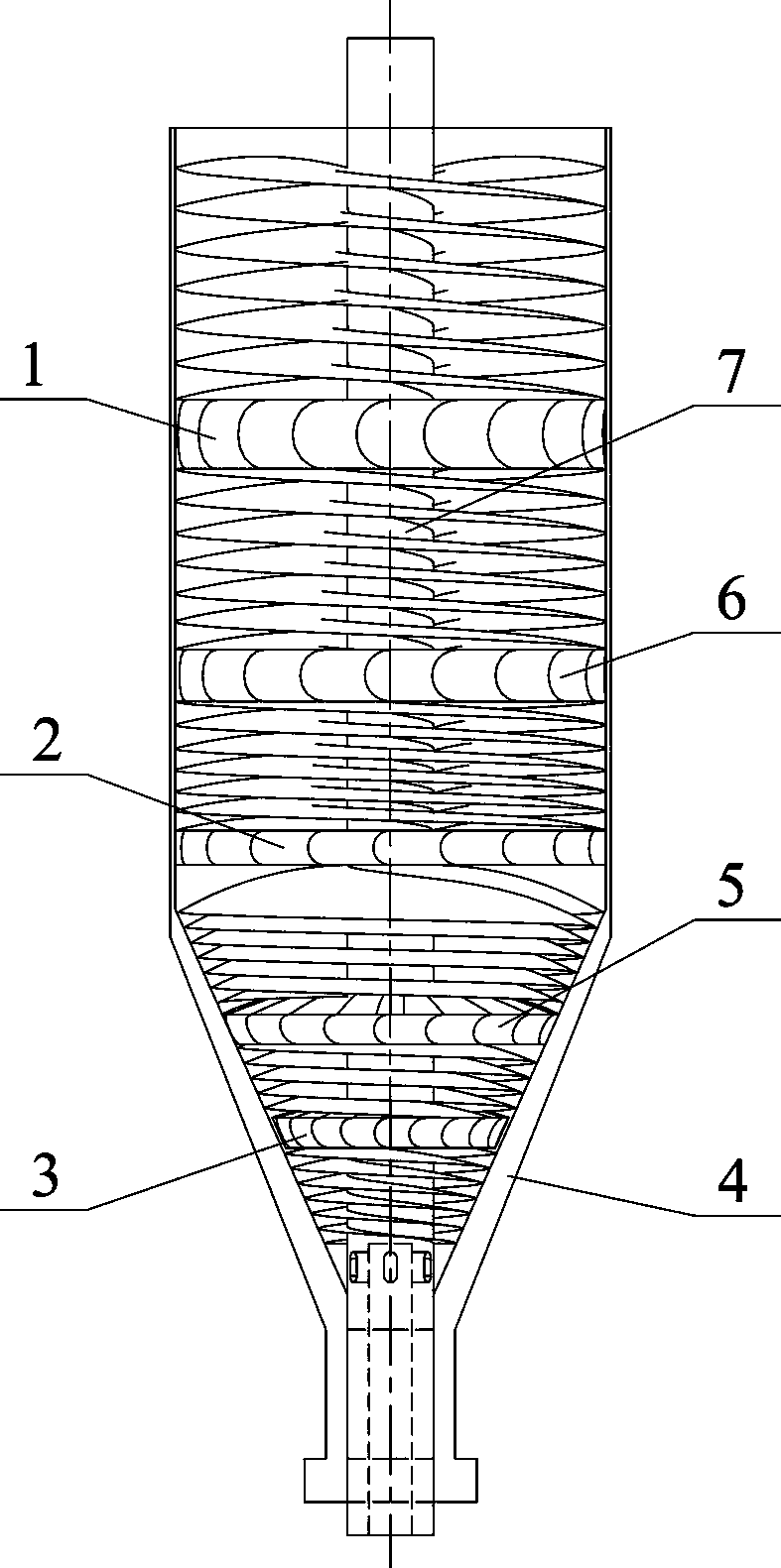
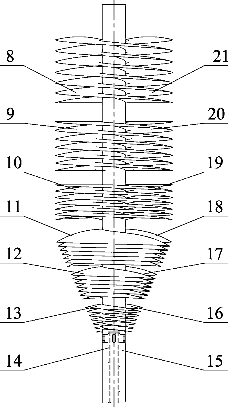
[0020] Manufacture variable-pitch screw compressor heads for screw compression expansion refrigerators, including the first horizontal diffuser ring (1), the third horizontal diffuser ring (2), the second conical diffuser ring (3), and the compression cover ( 4), the first conical diffuser ring (5), the second horizontal diffuser ring (6), the helical rotor (7); the helical rotor (7) includes the first blade of the first stage (8), the first blade of the second stage (9), the first blade of the third stage (10), the first blade of the fourth stage (11), the first blade of the fifth stage (12), the first blade of the sixth stage (13), the heat insulating sleeve (14), the central shaft ( 15), the sixth-level second blade (16), the fifth-level second blade (17), the fourth-level second blade (18), the third-level second blade (19), the second-level second blade (20), the first-level The second blade (21); the first conical diffuser ring (5) and the second conical diffuser ring (3...


PUM


Abstract

A variable pitch spiral compression machine head mainly comprises a dynamic spiral rotor with multistage vanes, multistage axial static diffuser rings and a static compression cover. By means of the method that the spiral ascent angle and the pitch of a spiral compression vane are adjusted stage by stage, the distance between adjacent spiral vanes and the passage section area are changed. By means of the multistage compression method that the spiral vanes rotating at a high speed press in a centrifugal mode stage by stage and the method that the multistage diffuser rings are arranged axially and diffuse pressure axially, the process that gas is pressed in a centrifugal mode and pressurized stage by stage is achieved. A high pressure ratio can be generated, high pressure can be borne, the diameter of a cylinder of a compressor is reduced, and miniaturization of the compressor is facilitated. The number of the spiral vanes of the compressor, the diameter of a base circle, the number of compression stages, the pitch of the spiral vanes and other important design parameters can be determined according to compressible performance of actual gas and the pressure ratio of the gas, and the compressor can be designed flexibly. By means of the long cylindrical compression machine head, the heat conductive area of the cylinder is increased, the compression process is close to the constant-temperature compression process, and compression work is reduced.

Description

technical field [0001] The invention relates to a variable-pitch screw compressor head for a screw compression-expansion refrigerator. By changing the pitch of the screw compression blades and the rising angle of the screw step by step, and the continuous compression method of step-by-step expansion and recompression, the high-speed helical impeller can achieve more gas compression. Stage centrifugal stamping compression process. The variable pitch screw compressor head is mainly used in the screw compression expansion refrigerator. It is the compression equipment of the screw compression expansion refrigerator. It uses the method of gradually adjusting the pitch of the spiral compression impeller blades to change the distance between adjacent spiral blades and the cross-sectional area of ​​the flow. The step-by-step centrifugal stamping process of refrigerant gas is realized by adopting the multi-stage compression method of step-by-step centrifugal stamping of high-speed rota...

Claims


Application Information

Patent Timeline
Patent Type & Authority Applications(China)
IPC IPC(8): F04C18/16F04C28/00F04C29/00
Inventor 张周卫汪雅红张小卫吴金群薛佳幸
Owner 张周卫
Why Eureka
Try Eureka